


BOSCH REXROTH
R928036311
- BOSCH REXROTH
- Material:R928036311
- Model:7SL180 H20XL-S00-010-R0M00
Due to extremely high demand, please call 877-366-7226 for availability
The Bosch Rexroth 7 SL 180 H20XL-S00-010-R0M00 (R928036311) is a high-performance cartridge filter designed for inline installation within hydraulic systems. This filter is optimized for mobile hydraulics, offering a space-saving and service-friendly solution. It can be directly installed in suction, pressure, or return lines to protect upstream components from contamination. The unit comprises a filter head and one or two screwed replacement cartridges, depending on the size, which include an integrated filter element. The filter media used in this model is specially engineered to remove very fine particles while providing a high dirt holding capacity, ensuring thorough cleaning of the hydraulic fluid. For enhanced monitoring and maintenance, the 7 SL 180 H20XL-S00-010-R0M00 can be equipped with various indicators such as vacuum meters or switches for suction lines, pressure gauges or switches for return lines, and pressure differential switches for pressure lines. These indicators facilitate timely maintenance by signaling when the filter element requires replacement. Additionally, this Bosch Rexroth cartridge filter may include an optional bypass valve integrated into the housing. This valve is a safety feature that allows part of the flow to reach the clean side of the filter without being filtered if there's an increase in pressure differential—usually due to a clogged filter element—and if the maintenance indicator is not heeded. However, it's critical to note that when the bypass valve is engaged, effective filtration is compromised. Overall, this particular model provides robust protection for hydraulic circuits by ensuring contaminants are efficiently removed from the fluid stream. Its design caters to applications where space efficiency and ease of service are priorities without compromising filtration effectiveness.
General information:
The replacement cartridge filter is suitable for direct installation in suction, pressure or return lines. It is installed upstream components to be protected.
It basically consists of a filter head (1) and a screwed replacement cartridge (2) with integrated filter element (and/or two replacement cartridges for size 180 and 260).
Optionally, a maintenance indicator (3) and/or a bypass valve (4) are configurable for the filter.
Via the inlet, the fluid reaches the replacement cartridge (2) where it is cleaned. The dirt particles filtered out settle in the filter element. Via the outlet, the filtered fluid enters the hydraulic circuit. With sizes 180 and 260, there is simultaneous flow through both replacement cartridges.
Maintenance indicator:
Special maintenance indicators are possible for the following applications:
Suction line: vacuum meter or vacuum switch Return line: pressure gauge or pressure switch Pressure line: pressure differential switchThe relevant position of the maintenance indicator is shown in chapter “Dimensions”.
Notice:
If the maintenance indicator for the replacement cartridge exchange is not observed, the bypass valve will open if the pressure differential increases. In this way, one part of the flow reaches the clean side of the filter without being filtered. Thus, effective filtration is no longer guaranteed.
7 SL 30 … 60
7 SL 90 … 130

|
01 |
02 |
03 |
04 |
05 |
06 |
07 |
08 |
09 |
10 |
11 |
12 |
|||
|
7 |
SL |
‒ |
S00 |
‒ |
0 |
‒ |
M |
0 |
0 |
|
Pressure |
|||||
|
01 |
Spin-on filter 7 bar |
7 |
|||
|
Series |
|||||
|
02 |
Spin-on filter without isolator valve |
SL |
|||
|
Size |
|||||
|
03 |
7 SL... |
30/21 |
|||
|
45/21 |
|||||
|
60/21 |
|||||
|
90 |
|||||
|
130 |
|||||
|
180 1) |
|||||
|
260 2) |
|||||
|
Filter rating in μm |
|||||
|
04 |
Absolute |
Glass fiber material, not cleanable |
H3XL |
||
|
H6XL |
|||||
|
H20XL |
|||||
|
Glass fiber material generation 5, non-reusable, not cleanable |
PWR10... |
||||
|
Nominal |
Paper, not cleanable |
P10 |
|||
|
P25 |
|||||
|
Pressure differential |
|||||
|
05 |
Max. admissible pressure differential of the filter element 5 bar |
S00 |
|||
|
Solenoid |
|||||
|
06 |
Without |
0 |
|||
|
Bypass valve |
|||||
|
07 |
Without |
0 |
|||
|
Cracking pressure 0,3 bar ‒ with maintenance indicator C; F0.2; G0.2 configurable |
1 |
||||
|
Cracking pressure 2,5 bar ‒ with maintenance indicator A; D1,5; H1,5; J1,5; P1,5 configurable |
5 |
||||
|
Maintenance indicator |
|||||
|
08 |
Without |
0 |
|||
|
Pressure gauge 0 … 6 bar |
A 3) |
||||
|
Vacuum meter -1 … 0,6 bar |
C |
||||
|
Back pressure indicator, visual |
D1,5 |
||||
|
Vacuum switch normally open contact |
F0,2 |
||||
|
Vacuum switch normally closed contact |
G0,2 |
||||
|
Pressure switch normally open contact |
H1,5 |
||||
|
Vacuum switch normally closed contact |
J1,5 |
||||
|
Pressure differential indicator visual/electrical with connector (only for sizes 90…260) |
P1,5 |
||||
|
Connection |
|||||
|
09 |
Frame size |
7 SL 30/21…60/21 |
7 SL 90…130 |
7 SL 180…260 |
|
|
Connection |
|||||
|
ISO 228 |
G3/4 |
G1 1/4 |
G1 1/2 |
R0 |
|
|
SAE flange |
SAE 1 1/2″ |
S0 |
|||
|
SAE J1926 |
SAE 20 |
U0 |
|||
|
Seal |
|||||
|
10 |
NBR |
M |
|||
|
Housing material |
|||||
|
11 |
Standard material |
0 |
|||
|
Supplementary information |
|||||
|
12 |
Without |
0 |
|||
|
1) |
Filter size 180 comprises two replacement cartridges of size 90. |
||||
|
2) |
Filter size 260 comprises two replacement cartridges of size 130. |
||||
|
3) |
If a pressure gauge is used, the maximum admissible operating pressure is reduced to 6 bar. |
||||
|
Further versions (filter materials, connections,...) are available upon request. |
|||||
For applications outside these parameters, please consult us!
general
|
Size |
30/21 | 45/21 | 60/21 | 90 | 130 | 180 | 260 | ||
|
Installation position |
Vertical | ||||||||
|
Ambient temperature range |
°C |
-40 … +65 | |||||||
|
Storage conditions 1) |
Seal |
°C |
-40 ... +65 | ||||||
|
Weight |
kg |
0.8 | 0.9 | 1.1 | 1.6 | 1.9 | 3 | 3.2 | |
|
Volume |
l |
0.5 | 1.2 | 2 | 2.7 | 2x2 | 2x2.7 | ||
|
Material |
Filter head |
Aluminium | |||||||
|
Replacement cartridge |
Steel | ||||||||
|
Maintenance indicator |
Aluminum / / plastic / steel | ||||||||
| 1) | max. relative air humidity 65 % |
hydraulic
|
Size |
30/21 | 45/21 | 60/21 | 90 | 130 | 180 | 260 | |
|
Operating pressure |
bar |
7 | ||||||
|
Hydraulic fluid temperature range |
°C |
-10 … +100 | ||||||
|
cold start temperature range 1) |
°C |
40 ... 10 | ||||||
|
Minimum conductivity of the medium |
pS/m |
300 | ||||||
|
Fatigue strength according to ISO 10771 |
Load cycles |
> 10⁶ with operating pressure | ||||||
| 1) | During the cold start up, expect a sudden pressure increase and a flow of at least 50% in each case. A bypass valve is essential. |
Maintenance indicator
|
Type |
Pressure gauge 0 … 6 bar | Vacuum meter -1 … 0,6 bar | Optical | Pressure differential indicator visual/electrical | Back pressure indicator electrical | Vacuum switch electrical | ||||
|
Version |
M010 | M070 | P1,5000000M | F1,5GW0200M | H1,5HS3200M | H1,5HA3200M | I0,2HS3200V | I0,2HA3200V | ||
|
Contact load, direct voltage |
Amax. |
0.25 A | 4 A | |||||||
|
Voltage range |
Vmax. |
175 AC/DC | 42 AC | |||||||
|
Maximum switching power |
VA |
5 | 100 | |||||||
|
Switching type |
100 % signal |
Changeover | Normally open contact | Normally closed contact | Normally open contact | Normally closed contact | ||||
|
Protection class according to DIN EN 60529 |
- | IP65 | IP 54 | |||||||
|
Ambient temperature range |
°C |
-10 … +60 | -10 … +85 | -10 … +100 | -20 … +85 | -10 … +70 | -20 … +70 | |||
|
Operating temperature range |
°C |
-10 … +60 | -10 … +85 | -10 … +100 | -20 … +100 | -10 … +100 | -20 … +100 | |||
|
Weight |
kg |
0.06 | 0.05 | 0.02 | 0.3 | 0.1 | 0.17 | |||
|
Material |
Housing |
Plastic / brass | Plastic/ steel / phosphor bronze | Aluminum / / plastic / steel | Aluminum / / plastic / brass | Steel | Brass | |||
|
Seals |
NBR | FKM | ||||||||
For direct voltage above 24 V, spark extinguishing is to be provided for protecting the switching contacts.
Filter element
|
Glass fiber material, H...XL |
Single-use element on the basis of inorganic fiber |
||
|
Filtration ratio according to ISO 16889 up to Δp = 5.0 bar |
Achievable oil cleanliness according to ISO 4406 [SAE-AS 4059] |
||
|
Particle separation |
H20XL |
ß20(c) ≥ 200 |
19/16/12 ... 22/17/14 |
|
PWR10 |
ß10(c) ≥ 200 |
17/14/10 ... 21/16/13 |
|
|
H6XL |
ß6(c) ≥ 200 |
15/12/10 ... 19/14/11 |
|
|
H3XL |
ß5(c) ≥ 200 |
13/10/8 ... 17/13/10 |
|
|
Admissible pressure differential in bar |
- S00 |
5 bar |
|
Compatibility with permitted hydraulic fluids
|
Hydraulic fluid |
Classification |
Suitable sealing materials |
Standards |
|
Mineral oil |
HLP |
NBR |
DIN 51524 |
Filter element (measured with mineral oil HLP46 according to DIN 51524)
Spec. weight: < 0.9 kg/dm3
Δp-Q characteristic curves for complete filter, recommended initial Δp for design = 0.5 bar
Selection of the perfect filter is made possible by our online “Bosch Rexroth FilterSelect“ design software.
7 SL 30

7 SL 45

7 SL 60

7 SL(S) 90
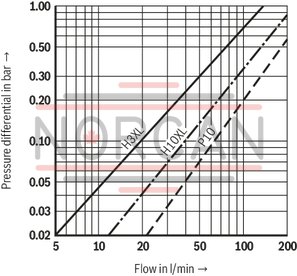
7 SL(S) 130
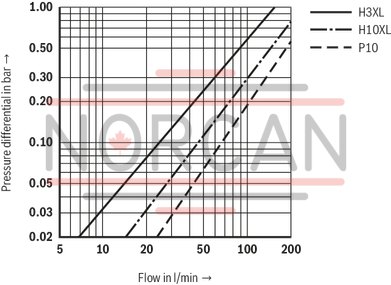
7 SL(S) 180

7 SL(S) 260
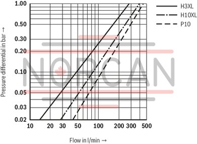
|
Spare part |
Back pressure gauge M 010 |
Vacuum gauge M 070 |
Optical/mechanical P1,5000000M |
Pressure switch Normally open contact H1,5 HS 32 00M Normally closed contact H1,5 HA 32 00M |
Vacuum switch Normally open contact I0,2 HS 32 00V Normally closed contact I0,2 HA 32 00V |
Optical/electrical - with connector |
|
Drawing |

|

|

|

|

|

|
|
Ordering code |
A |
C |
D |
Normally open contact H Normally closed contact J |
Normally open contact F Normally closed contact G |
Changeover P |
|
Symbol |

|

|
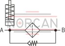
|

|

|

|
7 SL 30 … 60
7 SL 90 … 130
7 SLS 90 … 130

|
Filter type |
I |
II |
III |
IV |
WA - flange connection |
A1 |
A2 |
A3 |
A4 |
B1 |
B2 |
C1 |
⌀C2 |
C3 |
D1 |
E1 |
Connection spin-on element |
Installation position - maintenance indicator |
||||||||||||||||
|
R... |
S... |
U... |
A |
C |
D1,5 |
F0,2 |
G0,2 |
H1,5 |
SAE J1926 |
P1,5 |
A |
C |
D1,5 |
F0,2 |
G0,2 |
H1,5 |
SAE J1926 |
P1,5 |
||||||||||||||||
|
mm |
mm |
mm |
mm |
mm |
mm |
mm |
mm |
mm |
mm |
mm |
mm |
mm |
mm |
mm |
mm |
M010 |
M070 |
P1,5 |
I0,2HS3200M |
I0,2HA3200M |
H1,5HS3200M |
H1,5HA3200M |
F1,5GW0200M |
|||||||||||
| 7 SL 30 ... 60 | G1/8 | G1/8 | G1/8 | G1/8 | not possible | - | IV | III | II | I | I | II | II | - | ||||||||||||||||||||
| 7 SL 90 ... 130 | - | optional | II | Flange connection | ||||||||||||||||||||||||||||||
| 7 SL 30/21 | 95 | 41 | 20 1) | 20 | 95 | 38 | G3/4 | - | - | 92 | M8 | 10 | 54 | 54 | 118 | 116 | 116 | 99 | 99 | G3/4 | ||||||||||||||
| 7 SL 45/21 | 146 | |||||||||||||||||||||||||||||||||
| 7 SL 60/21 | 205 | |||||||||||||||||||||||||||||||||
| 7 SL 90 | 183 | 69 | 40 | 133 | 48 | G1 1/4 | 1 5/8-12 UN | 128 | 15 | 72 | 72 | 124 | 122 | 122 | 117 | 117 | 107 | G1 1/4 | ||||||||||||||||
| 7 SL 130 | 231 | |||||||||||||||||||||||||||||||||
| 1) | Servicing height for spin-on element |
7 SL 180 … 260
7 SLS 180 … 260

|
Filter type |
I |
WA - flange connection |
A1 |
A2 |
A3 |
A4 |
B1 |
B2 |
B3 |
B4 |
C1 |
⌀C2 |
C3 |
D1 |
E1 |
Connection spin-on element |
Installation position - maintenance indicator |
|||||||||||||
|
R... |
S... |
U... |
A |
D1,5 |
H1,5 |
SAE J1926 |
P1,5 |
A |
C |
D1,5 |
F0,2 |
G0,2 |
H1,5 |
SAE J1926 |
P1,5 |
|||||||||||||||
|
mm |
mm |
mm |
mm |
mm |
mm |
mm |
mm |
mm |
mm |
mm |
mm |
mm |
mm |
mm |
M010 |
M070 |
P1,5 |
I0,2HS3200M |
I0,2HA3200M |
H1,5HS3200M |
H1,5HA3200M |
F1,5GW0200M |
||||||||
| 7 SL 180 ... 260 | G1/8 | Possible | - | II | - | II | - | - | II | II | Flange connection | |||||||||||||||||||
| 7 SL 180 | 183 | 90 | 20 1) | 44 | 150 | 94 | 60 | 120 | G1 1/2 | SAE 1 1/2″, 3000 psi | - | 128 | M12 | 15 | 140 | 204 | 185 | 185 | 175 | G1 1/4 | ||||||||||
| 7 SL 260 | 231 |
SAE 1 1/4″, 3000 psi SAE 1 1/2″, 3000 psi |
||||||||||||||||||||||||||||
| 1) | Servicing height for spin-on element |
Installation
The max. operating pressure of the system must not exceed the max. admissible operating pressure of the filter (see name plate). During assembly of the filter, the flow direction (see direction arrows) and the required servicing height of the replacement cartridge (see chapter “Dimensions”) are to be considered. Easy cartridge exchange is guaranteed in the installation position ‒ replacement cartridge vertically downwards ‒ . The maintenance indicator must be arranged in a well visible way. Remove the plastic plugs at the filter inlet and outlet. The electric maintenance indicator is connected via a mating connector which is plugged onto the contacts of the maintenance indicator and held by means of a screw and/or in the order version H, J, F and G, directly applied to the contacts with a rubber bushing.Commissioning
Commission the system.
Notice:
There is no bleeding provided at the filter.
If at operating temperature, the red indicator pin reaches out of the mechanical/visual maintenance indicator or if the switching process in the electronic indicator is triggered, the replacement cartridge is contaminated and needs to be replaced.Notice:
With sizes 180 and 260, two replacement cartridges are flown through simultaneously; both of them have to be exchanged in case of maintenance.
The material number of the corresponding replacement exchange cartridge is indicated on the name plate of the complete filter. It must comply with the material number on the replacement cartridge. Decommission the system. The operating pressure is to be built up on the system side.Notice:
There is no bleeding provided at the filter.
Screw off the replacement cartridge.Notice:
With sizes 180 and 260, two replacement cartridges are flown through simultaneously; both of them have to be exchanged in case of maintenance.
Screw on the new replacement cartridge hand-tight.Please note:
If necessary, tighten further carefully in the depressurized condition (using a band wrench, if applicable)
Commission the system. If fluid leaks after commissioning between replacement cartridge and filter head, the replacement cartridge has to be re-tightened. Assembly and disassembly only with depressurized system! Tank is under pressure! Remove the replacement cartridge only if it is depressurized! Do not exchange the maintenance indicator while the filter is under pressure! If the flow direction is not considered during the assembly, the filter element will be destroyed. Particles will get into the system and damage downstream components.Notes:
All works at the filter only be trained specialists. Functioning and safety are only guaranteed if original Bosch Rexroth filter elements and spare parts are used. Warranty becomes void if the delivered item is changed by the ordering party or third parties or improperly mounted, installed, maintained, repaired, used or exposed to environmental condition that do not comply with the installation conditions.Tightening torques
|
Series 7 SL... |
30/21 |
45/21 |
60/21 |
90 |
130 |
180 |
260 |
||
|
Screw/tightening torque with |
Nm |
max. |
6 Nm |
10 Nm |
20 Nm |
||||
|
Mounting screws |
2 x M8 |
3 x M12 |
|||||||
|
Minimum screw-in depth |
mm |
8 mm |
12 mm |
10 mm |
|||||
Tightening torques
|
Maintenance indicator |
M010 |
M070 |
P1,5000000M |
F1,5GW0200M |
H1,5HS3200M |
H1,5HA3200M |
I0,2HS3200V |
I0,2HA3200V |
||
|
Screw/tightening torque with |
Nm |
max. |
conically sealing / no information possible |
20 Nm |
40 Nm |
20 Nm |
||||
|
Quantity |
- |
4 |
- |
|||||||
Classification according to the Pressure Equipment Directive
The replacement cartridge filters for hydraulic applications are pressure holding equipment according to article 1, section 2.1.4 of the Pressure Equipment Directive 97/23/EC (PED). However, on the basis of the exception in article 1, section 3.6 of the PEG, hydraulic filters are exempt from the PED if they are not classified higher than category I (guideline 1/19).
For the classification, fluids from the chapter “Compatibility with permitted hydraulic fluids” have been taken into consideration.
They do not receive a CE mark.
Use in potentially explosive areas according to directive 94/9/EC (ATEX)
The replacement cartridge filters without maintenance indicator and/or with mechanical/visual maintenance indicator are no equipment or components in the sense of directive 94/9/EC and are not provided with a CE mark. It has been proven with the ignition risk analysis that these replacement cartridge filters do not have own ignition sources according to DIN EN 13463-1:2009.
The replacement cartridge filters and the mechanical/visual maintenance indicators can be used for the following potentially explosive areas:
|
Zone suitability |
||
|
Gas |
1 |
2 |
|
Dust |
21 |
22 |
Complete filter with mech./opt. maintenance indicator, pressure gauge, vacuum meter
|
Use/assignment |
II 2G | II 2D | ||
|
Assignment |
Ex II 2G c IIB TX | Ex II 2D c IIB TX | ||
|
Minimum conductivity of the medium |
pS/m |
300 | ||
|
Dust accumulation |
max. |
mm |
- | 0.5 |