


BOSCH REXROTH
R928044866
- BOSCH REXROTH
- Material:R928044866
- Model:40FLEN1000 H6XL-A00-00V22-S0M00
Due to extremely high demand, please call 877-366-7226 for availability
The Bosch Rexroth 40 FLEN 1000 PWR6-A00-00V22-S0M00 (R928044866) is an advanced hydraulic filter designed for inline installation and is particularly well-suited for offline filtration applications. This product features an extremely large filter area, which ensures a high level of contaminant retention and prolonged service life. Engineered using state-of-the-art 3D computer-aided design, the filter boasts a flow-optimized structure that minimizes pressure drop across the system, thus maintaining hydraulic efficiency. The special highly efficient filter media employed in this model enhances the filtration process, capturing even the smallest particles to protect sensitive hydraulic components from contamination. The design and materials used in the construction of this filter ensure reliability and durability in various operating conditions. The Bosch Rexroth 40 FLEN 1000 PWR6-A00-00V22-S0M00 is a testament to Bosch Rexroth's commitment to providing high-quality filtration solutions that meet the demanding requirements of modern hydraulic systems. Its capabilities make it an ideal choice for those seeking to maintain optimal cleanliness levels in their hydraulic circuits while extending the life of their equipment and reducing maintenance costs.
|
01 |
02 |
03 |
04 |
05 |
06 |
07 |
08 |
09 |
10 |
11 |
12 |
13 |
|||
|
40FLE |
‒ |
A |
‒ |
0 |
V2,2 |
‒ |
S0 |
|
Series |
|||
|
01 |
Inline filter 40 bar |
40FLE |
|
|
Filter element |
|||
|
02 |
with filter element according to DIN 24550 |
N |
|
|
Size |
|||
|
03 |
FLEN... |
0160 |
|
|
0250 |
|||
|
0400 |
|||
|
0630 |
|||
|
1000 |
|||
|
FLE... |
0045 |
||
|
0055 |
|||
|
0120 |
|||
|
0200 |
|||
|
0270 |
|||
|
Filter rating in μm |
|||
|
04 |
Nominal |
Stainless steel wire mesh, cleanable |
G10 |
|
G25 |
|||
|
Nominal |
Paper, not cleanable |
P10 |
|
|
Absolute |
Non-woven glass fiber media, not cleanable |
H3XL |
|
|
H20XL |
|||
|
Glass fiber material generation 5, non-reusable, not cleanable |
PWR10 |
||
|
Pressure differential |
|||
|
05 |
max. admissible pressure differential of the filter element 30 bar, with bypass valve 7 bar |
A |
|
|
Element design |
|||
|
06 |
Standard adhesive T = 100 °C |
0… |
|
|
Standard material |
…0 |
||
|
chemically nickel-plated |
…D 1) |
||
|
Solenoid |
|||
|
07 |
Without |
0 |
|
|
Bypass valve |
|||
|
08 |
Without |
0 |
|
|
3.5 bar |
7 |
||
|
Maintenance indicator |
|||
|
09 |
Maintenance indicator, mech./visual, switching pressure 2.2 bar |
V2,2 |
|
|
Connection |
|||
|
10 |
SAE flange |
S0 |
|
|
Seal |
|||
|
11 |
NBR |
M |
|
|
FKM |
V |
||
|
Material |
|||
|
12 |
Standard |
0 |
|
|
chemically nickel-plated |
D 1) |
||
|
Supplementary information |
|||
|
13 |
Without |
0 |
|
|
Manufacturer's inspection certificate M according to DIN 55350 T18 Z1 |
Z |
||
|
1) |
Only in connection with FKM seal |
||
|
Further versions (filter materials, connections,...) are available upon request. |
|||
general
|
Size |
0045 | 0055 | 0120 | 0200 | 0270 | 0250 | 0400 | 0630 | 1000 | ||||
|
Ambient temperature range |
ϑ |
°C |
-30 … +100 | ||||||||||
|
Weight |
m |
kg |
19 | 23 | 27.4 | 60 | 70 | 12 | 13.2 | 19.5 | 21.9 | 50 | |
|
Volume |
l |
4.8 | 6.8 | 14 | 22 | 28 | 1.4 | 2.7 | 4 | 7.1 | 12 | ||
|
Material |
Seals |
NBR or FKM | |||||||||||
|
Hydraulic fluid |
Classification |
Suitable sealing materials |
Suitable adhesive |
Standards |
|
|
Mineral oil |
HLP |
NBR |
Standard |
DIN 51424 |
|
|
Bio-degradable |
Insoluble in water |
HETG |
NBR |
VDMA 24568 |
|
|
HEES |
FKM |
||||
|
Soluble in water |
HEPG |
FKM |
VDMA 24568 |
||
|
Flame-resistant |
Water-free |
HFDU, HFDR |
FKM |
VDMA 24317 |
|
|
Containing water |
HFAS |
NBR |
DIN 24320 |
||
|
HFAE |
NBR |
||||
|
HFC |
NBR |
VDMA 24317 |
|||
|
Skydrol |
‒ |
EPDM |
Special “H” |
‒ |
|
Important information on hydraulic fluids!
For more information and data on the use of other hydraulic fluids, please refer to data sheet 90220 or contact us! Flame-resistant – containing water: Due to possible chemical reactions with materials or surface coatings of machine and system components, the service life with these hydraulic fluids may be less than expected. Filter materials made of filter paper P must not be used, filter elements with glass fiber material have to be used instead. Bio-degradable: If filter materials made of filter paper are used, the filter life may be shorter than expected due to material incompatibility and swelling.hydraulic
|
Size |
0045 | 0055 | 0120 | 0200 | 0270 | 0250 | 0400 | 0630 | 1000 | |||
|
Operating pressure |
pmax |
bar |
40 | |||||||||
For applications outside these parameters, please consult us!
Filter element (measured with mineral oil HLP46 according to DIN 51524)
Spec. weight: < 0.9 kg/dm3
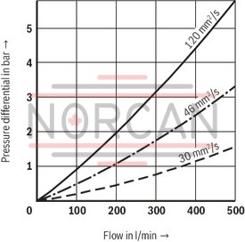
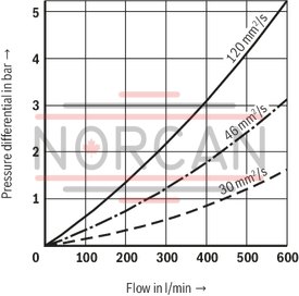
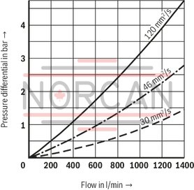
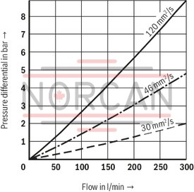
Δp-Q characteristic curves for complete filter, recommended initial Δp for design = 0,8 bar
Selection of the perfect filter is made possible by our online “Bosch Rexroth FilterSelect“ design software.
40FLE0045-H3XL
40FLE0055-H3XL
40FLE0120-H3XL
40FLEN0160-H3XL
40FLE0200-H3XL
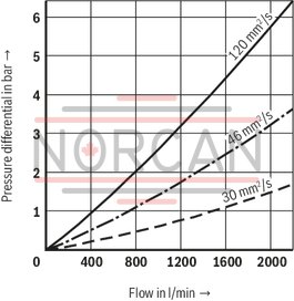
40FLEN0250-H3XL
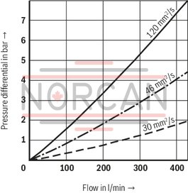
40FLE0270-H3XL
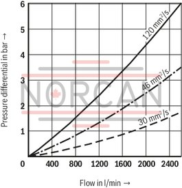
40FLEN0400-H3XL
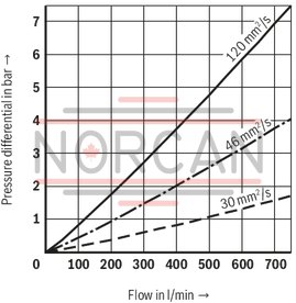
40FLEN0630-H3XL
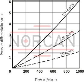
40FLEN1000-H3XL
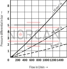
40FLE0045-H10XL
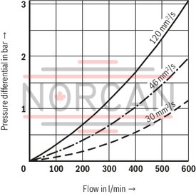
40FLE0055-H10XL
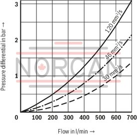
40FLE0120-H10XL
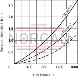
40FLEN0160-H10XL
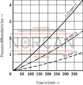
40FLE0200-H10XL
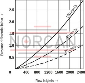
40FLEN0250-H10XL
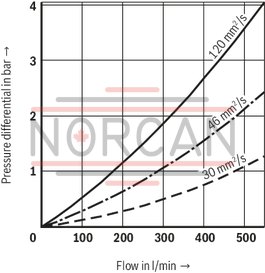
40FLE0270-H10XL
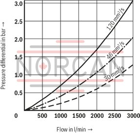
40FLEN0400-H10XL
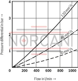
40FLEN0630-H10XL
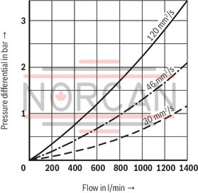
40FLEN1000-H10XL
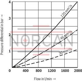
40FLEN0160…0630
40FLE0045…0120
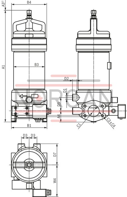
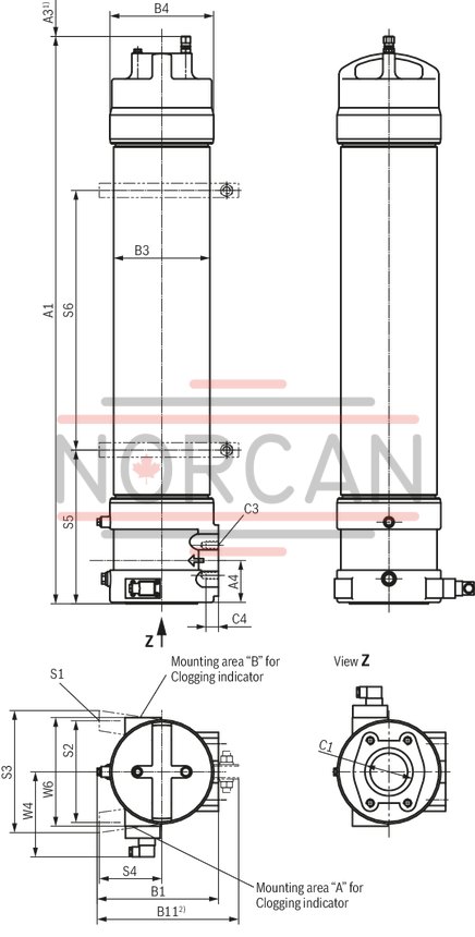
40FLEN1000
40FLE0200…0270
|
NG |
A1 |
A3 1) |
A4 |
B1 |
ØB3 |
ØB4 |
B11 |
C1 - Standard |
C3 |
C4 |
D1 |
D2 |
D3 |
D5 |
D7 |
ØS1 |
S2 |
S3 |
S4 |
S5 |
S6 |
W4 |
W6 |
|
mm |
mm |
mm |
mm |
mm |
mm |
mm |
mm |
mm |
mm |
mm |
mm |
mm |
mm |
mm |
mm |
mm |
mm |
mm |
mm |
||||
| 0045 | 663 | 400 | 49.5 | 160 | 140 | 158 | SAE 2", 3000 psi DN50 | M16 | 21 | M16 | 22 | 35 | 60 | 95 | 143 | ||||||||
| 0055 | 831 | 568 | 49.5 | 160 | 140 | 158 | SAE 2", 3000 psi DN50 | M16 | 21 | M16 | 22 | 35 | 60 | 95 | 143 | ||||||||
| 0120 | 1050 | 750 | 61.5 | 195 | 170 | 188 | SAE 3", 3000 psi DN80 | M16 | 21 | M16 | 20 | 45 | 70 | 105 | 155 | ||||||||
| 0200 | 948 | 750 | 90 | 226 | 200 | 216 | 294.5 2) | SAE 4", 3000 psi DN100 | M16 | 26 | 9 | 212 | 254 | 108 | 320 | 310 | 184 | 226 | |||||
| 0270 | 1182 | 990 | 90 | 226 | 200 | 216 | 294.5 2) | SAE 4", 3000 psi DN100 | M16 | 26 | 9 | 212 | 254 | 108 | 320 | 540 | 184 | 226 | |||||
| 411 | 160 | 49.5 | 160 | 140 | 158 | SAE 2", 3000 psi DN50 | M12 | 21 | M16 | 22 | 35 | 60 | 95 | 143 | |||||||||
| 0250 | 501 | 250 | 49.5 | 160 | 140 | 158 | SAE 2", 3000 psi DN50 | M12 | 21 | M16 | 22 | 35 | 60 | 95 | 143 | ||||||||
| 0400 | 543 | 250 | 61.5 | 195 | 170 | 188 | SAE 3", 3000 psi DN80 | M16 | 21 | M16 | 20 | 45 | 70 | 105 | 155 | ||||||||
| 0630 | 693 | 400 | 61.5 | 195 | 170 | 188 | SAE 3", 3000 psi DN80 | M16 | 21 | M16 | 20 | 45 | 70 | 105 | 155 | ||||||||
| 1000 | 590 | 630 | 90 | 226 | 200 | 216 | 294.5 2) | SAE 4", 3000 psi DN100 | M16 | 26 | 9 | 212 | 254 | 108 | 260 | 65 | 184 | 226 |
| 1) | Servicing height for filter element exchange |
| 2) | Total width with clamp |
Filter installation
Compare operating overpressure with name plate information. Screw filter housing to the mounting device considering flow direction (direction arrows) and servicing height of the filter element. Remove the blanking plugs from filter inlet and outlet, screw filter into the pipeline, ensure that the system is assembled without tension stress.
Warning!
Assembly and disassembly only with depressurized system! Tank is under pressure! When removing the filter, it has to be ensured that filter inlet and filter outlet have to be drained separately! Remove the filter bowl only if it is depressurized! Do not exchange the maintenance indicator while the filter is under pressure! Functional and safety warranty only applicable when using genuine Rexroth spare parts! Maintenance only be trained personnel!
Commissioning
Switch on system pump. Bleed filter by opening the bleed screw; close when operating medium escapes.
Maintenance
If at operating temperature, the red indicator pin reaches out of the maintenance indicator and/or if the switching process in the electronic indicator is triggered, the filter element is contaminated and needs to be replaced and cleaned respectively.
Filter element exchange
Switch off system pump.
Open the bleed screw and reduce the pressure.
Open the plug screw and allow contaminated oil to drain from the filter housing. Screw off the filter head / filter cover and remove the filter element from the spigot in the filter bowl by turning it slightly and remove it from the filter housing
Close the plug screw again.
Replace the filter elements H...-XL and P..., clean the filter element with material G… . The efficiency of the cleaning process depends on the type of dirt and the amount of the pressure differential before the filter element exchange.
If the pressure differential after the filter element exchange exceeds 50 % of the value before the filter element exchange, the G… filter element needs to be replaced.
Rub the seal ring in the filter element with a little bit of oil. Re-install cleaned or replaced filter element in the filter housing by slightly rotating it back on its spigot. Ensure that the filter element is not damaged at the top end of the casing tube during installation.
Check seal ring item 7 in the casing tube and replace it in case of damage or wear. Screw on the filter head hand-tight, without auxiliary tool, to the last turn of thread; rotate back 1/4 rotation.
Complete the commissioning as described above.
Technical modifications reserved!
Three-part set-up consisting of filter bottom with inlet and outlet, casing tube as well as filter head that can be screwed off.
Further design variants are available upon request.
Filter element
Pleated design with optimized pleat density and various filter materials. The filter element is the most important component of the “FILTER” system with regard to the availability and the wear protection of the systems. Decisive criteria for the selection comprise the necessary cleanliness of the operating medium, the initial pressure differential and the dirt holding capacity. More detailed information is contained in our “Filter elements” prospectus.
Maintenance indicator
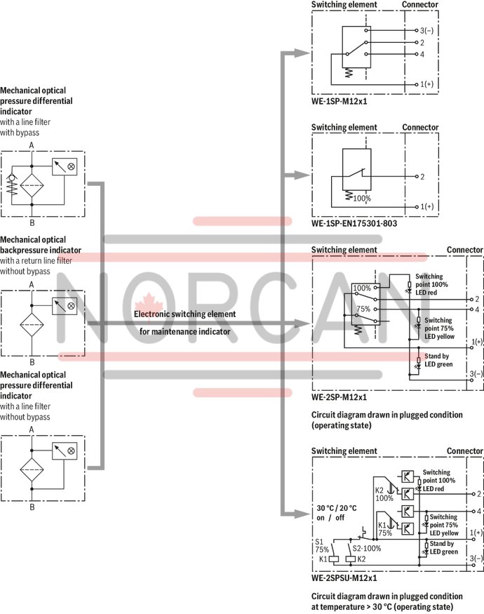
Basically, the filter is equipped with mechanical/visual maintenance indicator. The electronic maintenance indicator is connected via the electronic switching element with 1 or 2 switching points, which has to be ordered separately. The electronic switching element is attached to the mechanical/visual maintenance indicator and held by means of a locking ring.
Quality and standardization
The development, manufacture and assembly of BRFS industrial filters and BRFS filter elements is carried out within the framework of a certified quality management system in accordance with ISO 9001:2000. The pressure filters for hydraulic applications are pressure holding equipment according to article 1, section 2.1.4 of the Pressure Equipment Directive 97/23/EC (PED). However, on the basis of the exception in article 1, section 3.6 of the PEG, hydraulic filters are exempt from the PED if they are not classified higher than category I (guideline 1/19). They do not receive a CE mark.
Characteristic curves
A proper filter design is enabled by our software “Bosch Rexroth FilterSelect”, see download area http://www.boschrexroth.de. Additional characteristic curves for the filters in this catalog are contained in the BRFS filter calculation program.
Electronic switching elements
WE-.SP

Electronic switching elements
WE-.SP
Operating temperature -30 … +85 °CData sheet
Spare parts & repair
Electronic switching elements
WE-S02
Electronic switching elements
WE-S02
Max. operating pressure 40 bar Operating temperature -10 … +100 °CData sheet
Spare parts & repair
Pressure differential indicators for filters in pressure lines
WO-D01
Pressure differential indicators for filters in pressure lines
WO-D01
Max. operating pressure 450 bar Operating temperature -30 … +100 °CData sheet
Spare parts & repair
Backpressure indicators for return line filters
WO-S01
Backpressure indicators for return line filters
WO-S01
Max. operating pressure 10 bar Operating temperature -30 … +100 °CData sheet
Spare parts & repair
Backpressure indicators for return line filters
WO-S02
Backpressure indicators for return line filters
WO-S02
Max. operating pressure 10 bar Operating temperature -10 … +100 °CData sheet
Spare parts & repair