


BOSCH REXROTH
R978897745
- BOSCH REXROTH
- Material:R978897745
- Model:DZ6DP2-5X/210V/12
Quantity in stock: 0
The Bosch Rexroth DZ 6 DP2-5X/210V/12 (R978897745) is a direct operated pressure sequence valve designed to enable pressure-dependent connection of a second system by setting the sequencing pressure via an adjustment type. The valve's compression spring keeps the control spool in its initial position, blocking the valve until the pressure in channel P reaches the set value, at which point the control spool moves to allow flow from P to A without a pressure drop. This model features internal or external control signal options through channel P or port B X, and leakage oil discharge can be managed externally via port T Y or internally through A. It should be noted that with internal leakage oil discharge, there is an increase in set cracking pressure due to the pressure in channel A. Additionally, there is an option for a check valve for free hydraulic fluid return from channel A to channel P. The DZ 6 DP2-5X/210V/12 also offers a pressure gauge connection for monitoring sequencing pressure directly at the valve. This variant is designed for subplate mounting with porting patterns according to DIN form A (standard) and ISO with locating hole (ordering information). Subplates are available as a separate order. The product comes with various optional adjustment types including rotary knob, threaded pin with hexagon and protective cap, lockable rotary knob with scale, and rotary knob with scale. The valve size and component series X determine its maximum operating pressure and maximum flow rate capabilities. It's suitable for applications requiring precise control of hydraulic system sequencing where reliability and performance are critical.
Valve type DZ 6 DP is a direct operated pressure sequence valve. It is applied for pressure-dependent connection of a second system. The sequencing pressure is set via the adjustment type (4).
The compression spring (3) holds the control spool (2) in initial position, the valve is blocked. The pressure in channel P is applied via the control line (6) at the spool face of the control spool (2) opposite the compression spring (3).
If the pressure in channel P reaches the set value of the compression spring (3), the control spool (2) is moved to the left and the connection from P to A is opened. The system connected to channel A is connected without a pressure drop in channel P.
The control signal is received internally via the control line (6) from channel P or externally via port B (X).
Depending on the use of the valve, leakage oil discharge is realized externally via port T (Y) or internally via A.
Attention!
With internal leakage oil discharge, the set cracking pressure is increased by the pressure in channel A.
A check valve (5) can be optionally installed for free hydraulic fluid return flow back from channel A to channel P.
A pressure gauge connection (1) enables control of the sequencing pressure at the valve.
Type DZ 6 DP1–5X/…

Type DZ 6 DP1–5X/.XYM…

|
01 |
02 |
03 |
04 |
05 |
06 |
07 |
08 |
09 |
||
|
DZ 6 DP |
– |
5X |
/ |
* |
|
01 |
Pressure sequence valve NG6, direct operated |
DZ 6 DP |
|
Adjustment type |
||
|
02 |
Rotary knob |
1 |
|
Grub screw with hexagon and protective cap |
2 |
|
|
Lockable rotary knob with scale 1) |
3 |
|
|
Rotary knob with scale |
7 |
|
|
03 |
Component series 50 … 59 (50 … 59: unchanged installation and connection dimensions) |
5X |
|
04 |
Maximum sequencing pressure 25 bar |
25 |
|
Maximum sequencing pressure 75 bar |
75 |
|
|
Maximum sequencing pressure 150 bar |
150 |
|
|
Maximum sequencing pressure 210 bar |
210 |
|
|
Maximum sequencing pressure 315 bar |
3152) |
|
|
05 |
Internal pilot oil supply, internal leakage oil discharge |
no code |
|
External pilot oil supply, internal leakage oil discharge |
X |
|
|
Internal pilot oil supply, external leakage oil discharge |
Y |
|
|
External pilot oil supply, external leakage oil discharge |
XY |
|
|
06 |
With check valve |
no code |
|
Without check valve |
M |
|
|
Seal material |
||
|
07 |
NBR seals |
no code |
|
FKM seals (other seals upon request) |
V |
|
|
Observe compatibility of seals with hydraulic fluid used. |
||
|
08 |
Without locating hole |
no code |
|
With locating hole |
/603) |
|
|
09 |
Further details in the plain text |
* |
| 1) H-key with material no. R900008158 is included in the scope of delivery. | |
| 2) Only with adjustment type "2" and without check valve | |
| 3) Locking pin ISO 8752-3x8-St, material no. R900005694 (separate order) |
general
|
Size |
6 | ||
|
Weight (approx.) |
kg |
1.2 | |
|
Installation position |
any | ||
|
Ambient temperature range |
NBR seals |
°C |
-30 … +80 |
|
FKM seals |
°C |
-20 … +80 | |
hydraulic
|
Size |
6 | ||
|
Maximum operating pressure |
Port P |
bar |
315 |
|
Anschluss A |
bar |
315 | |
|
Port B (X) |
bar |
315 | |
|
Port T (Y) |
bar |
160 | |
|
Maximum sequencing pressure |
adjustable |
bar |
25 75 150 210 315 |
|
Maximum flow |
l/min |
60 | |
|
Hydraulic fluid |
see table | ||
|
Hydraulic fluid temperature range |
NBR seals |
°C |
-30 … +80 |
|
FKM seals |
°C |
-20 … +80 | |
|
Viscosity range |
mm²/s |
10 … 800 | |
|
Maximum admissible degree of contamination of the hydraulic fluid 1) |
Class 20/18/15 according to ISO 4406 (c) | ||
| 1) | The cleanliness classes specified for the components must be adhered to in hydraulic systems. Effective filtration prevents faults and simultaneously increases the life cycle of the components. For the selection of the filters, see www.boschrexroth.com/filter. |
|
Hydraulic fluid |
Classification |
Suitable sealing materials |
Standards |
|
|
Mineral oil |
HL, HLP |
FKM, NBR |
DIN 51524 1) |
|
|
Bio-degradable |
Insoluble in water |
HEES (synthetic esters) 2) |
FKM |
VDMA 24568 |
|
HETG (rape seed oil) 1) |
FKM, NBR |
|||
|
Soluble in water |
HEPG (polyglycols) 2) |
FKM |
VDMA 24568 |
|
|
Other hydraulic fluids on request |
||||
| 1) suitable for NBR and FKM seals | |
| 2) suitable for FKM seals only |
For applications outside these parameters, please consult us!
(measured with HLP46, ϑOil = 40 ±5 °C)
Δp-qV characteristic curves

Δp-qV characteristic curves
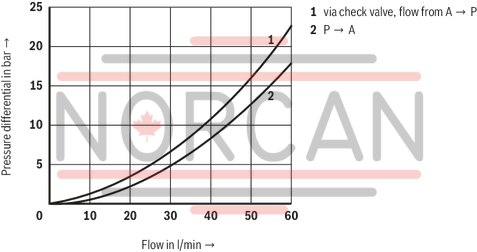
The characteristic curves apply for outlet pressure = zero in the entire flow range!
Version "no code"

Version “X"

Version “Y”

Version “XY"

Dimensions in mm

|
1 |
Name plate |
|
2 |
Adjustment type "1" |
|
3 |
Adjustment type "2" |
|
4 |
Adjustment type "3" |
|
5 |
Adjustment type "7" |
|
6 |
Dimensions required to remove the key |
|
7 |
Valve mounting bores |
|
8 |
Lock nut SW24 |
|
9 |
Hexagon SW10 |
|
10 |
Identical seal rings for ports A, B(X), P, T(Y) |
|
11 |
Pressure gauge connection G1/4; 12 mm deep; internal hexagon SW6 |
|
12 |
Without check valve |
|
13 |
With check valve |
|
14 |
Porting pattern according to DIN 24340 form A (without locating hole), or ISO 4401-03-02-0-05 (with locating hole for locking pin ISO 8752-3x8-St, material no. R900005694, separate order) |
Subplates (separate order)
(without locating hole)
G 341/01 (G1/4)
G 342/01 (G3/8)
G 502/01 (G1/2)
(with locating hole)
G 341/60 (G1/4)
G 342/60 (G3/8)
G 502/60 (G1/2)
Valve mounting screws (separate order)
4 hexagon socket head cap screws
ISO 4762 - M5 x 50 - 10.9-flZn-240h-L
Friction coefficient µtotal = 0.09 to 0.14,
Tightening torque MA = 7 Nm ± 10 %,
material no. R913000064
Pipe thread (G..) according to ISO 228/1