

BOSCH REXROTH
R978910249
$788.53 USD
- BOSCH REXROTH
- Material:R978910249
- Model:ZDR10DA1-5X/210YV/12
Quantity in stock: 0
The Bosch Rexroth ZDR10DA1-5X/210YV/12 (R978910249) is a direct operated pressure reducing valve designed for efficient control of system pressure. This sandwich plate valve is engineered to limit the secondary circuit's pressure by reducing the system pressure. It features a robust housing, a responsive control spool, and a durable compression spring for reliable operation. The secondary pressure can be precisely adjusted to meet specific requirements. This model includes an optional check valve, which allows free flow back from channel A to A in version A. The valve maintains its open position at initial start-up, enabling unrestricted flow from channel A to channel A while simultaneously applying pressure through the control line at the piston area against the compression spring. When the set value is exceeded, the control spool adjusts against the spring to maintain constant pressure levels in channel A. The ZDR10DA1-5X/210YV/12 also features internal supply of control signal and pilot oil via the control line from channel A. Should external forces increase pressure in channel A, the spool will further compress against the spring, connecting channel A with tank channel TB through a control edge on both spool and housing, allowing excess hydraulic fluid to discharge into the tank and preventing further pressure increases. An external leakage oil drain from the spring chamber is always present through channel TA. Additionally, a pressure gauge connection is available for monitoring secondary pressure directly at the valve. For different applications, version P reduces pressure in channel P with internal pilot oil supply from that same channel, while version B reduces pressure in channel P but extracts pilot oil from channel B—necessary if directional valves are used and secondary pressures must not be exceeded. The Bosch Rexroth ZDR10DA1-5X/210YV/12 valve offers versatility with its porting pattern compliant with ISO standards and multiple adjustment types including a rotary knob, sleeve with hexagon and protective cap, lockable rotary knob with scale, and rotary knob with scale. It accommodates various hydraulic requirements with its maximum operating pressures and flow rates specified for each size component series X.
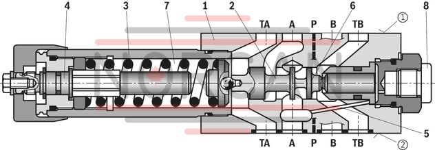
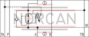
The valve type ZDR is a direct operated pressure reducing valve in sandwich plate design with pressure limitation of the secondary circuit. It is used to reduce the system pressure.
The pressure reducing valve basically comprises housing (1), control spool (2), compression spring (3), adjustment type (4) and an optional check valve.
The secondary pressure is set via the adjustment type (4).
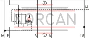
Version “A”
The valve is open in initial position. Hydraulic fluid can flow from channel A➀ to channel A➀ without restrictions. The pressure in channel A➀ is simultaneously applied via the control line (5) at the piston area opposite the compression spring (3). If the pressure in channel A➀ exceeds the value set at the compression spring (3), the control spool (2) is pushed against the compression spring (3) to control position and keeps the set pressure in channel A➀ at a constant level.
Control signal and pilot oil are supplied internally via the control line (5) from channel A➀.
If the pressure in channel A➀ increases further due to an external force effect at the actuator, it pushes the control spool (2) even further against the compression spring (3).
In this way, channel A➀ is connected to the tank (channel TB) via the control edge (6) at the control spool (2) and the housing (1). So much hydraulic fluid is discharged into the tank, that the pressure does not increase any further.
The leakage oil drain from the spring chamber (7) is always effected externally via channel TA.
A pressure gauge connection (8) allows for the control of the secondary pressure at the valve.
A check valve can be used for free flow back from channel A➀ to A➀ with version “A”.
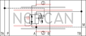
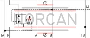
Versions “P” and “B”
For version “P”, the pressure reduction is effected in channel P➀. Control signal and pilot oil are supplied internally from channel P➀.
For version “B”, the pressure is reduced in channel P➀; but the pilot oil is extracted from channel B. If the directional valve is in spool position P to A, the pressure in channel B may not exceed the set secondary pressure. Otherwise, there is pressure reduction in channel A.
Attention!
If used without directional valve, channels TA and TB are connected to each other (e. g. in the cover plate). During set-up of a directional seat valve NG 10, a sandwich plate type HSZ10A078-3X/M00 (material no. R900537264) has to be used.Type ZDR 10 DA …
|
➀ |
component side |
|
➁ |
plate side |
|
01 |
Sandwich plate valve |
Z |
|
02 |
3-way pressure reducing valve |
DR |
|
03 |
Size 10 |
10 |
|
04 |
Direct operated |
D |
|
05 |
Pressure reduction in channel A➁ |
A |
|
Pressure reduction in channel P➁ (pilot oil supply from channel B) |
B |
|
|
Pressure reduction in channel P➁ |
P |
|
|
Adjustment type |
||
|
06 |
Rotary knob |
1 |
|
Sleeve with hexagon and protective cap |
2 |
|
|
Lockable rotary knob with scale |
3 1) |
|
|
Rotary knob with scale |
7 |
|
|
07 |
Component series 50 … 59 (50 … 59: unchanged installation and connection dimensions) |
5X |
|
08 |
Secondary pressure up to 25 bar |
25 |
|
Secondary pressure up to 75 bar |
75 |
|
|
Secondary pressure up to 150 bar |
150 |
|
|
Secondary pressure 210 bar |
210 |
|
|
09 |
Internal pilot oil supply, external pilot oil return |
Y |
|
10 |
With check valve (only version "A") |
no code |
|
Without check valve |
M |
|
|
Seal material |
||
|
11 |
NBR seals |
no code |
|
FKM seals (other seals upon request) |
V |
|
|
Observe compatibility of seals with hydraulic fluid used. |
||
|
12 |
Further details in the plain text |
* |
| 1) H-key with material no. R900008158 is included in the scope of delivery |
Preferred types and standard units are contained in the EPS (standard price list).
Notice!
To port X and Y bored according to ISO 4401-05-05-0-05 (e. g. for pilot-operated directional valve NG 10), version “SO30” applies at the end of the ordering code!
|
01 |
02 |
03 |
04 |
05 |
06 |
07 |
08 |
09 |
10 |
11 |
12 |
||
|
Z |
DR |
10 |
D |
– |
5X |
/ |
Y |
* |
general
|
Size |
10 | ||
|
Weight (approx.) |
kg |
2.8 | |
|
Installation position |
any | ||
|
Ambient temperature range |
NBR seals |
°C |
-30 … +80 |
|
FKM seal |
°C |
-20 … +80 | |
hydraulic
|
Size |
10 | ||
|
Maximum operating pressure |
Inlet |
bar |
315 |
|
Maximum secondary pressure |
Outlet |
bar |
25 75 150 210 |
|
Maximum counter pressure |
Port T |
bar |
160 |
|
Maximum flow |
l/min |
80 | |
|
Hydraulic fluid |
see table | ||
|
Hydraulic fluid temperature range |
NBR seals |
°C |
-30 … +80 |
|
FKM seal |
°C |
-20 … +80 | |
|
Viscosity range |
mm²/s |
10 … 800 | |
|
Maximum admissible degree of contamination of the hydraulic fluid 1) |
Class 20/18/15 according to ISO 4406 (c) | ||
| 1) | The cleanliness classes specified for the components must be adhered to in hydraulic systems. Effective filtration prevents faults and simultaneously increases the life cycle of the components. For the selection of the filters, see www.boschrexroth.com/filter. |
|
Hydraulic fluid |
Classification |
Suitable sealing materials |
Standards |
|
|
Mineral oils and related hydrocarbons |
HL, HLP, HLPD |
NBR, FKM |
DIN 51524 |
|
|
Environmentally compatible |
Insoluble in water |
HETG |
NBR, FKM |
ISO 15380 |
|
HEES |
FKM |
|||
|
Soluble in water |
HEPG |
FKM |
ISO 15380 |
|
|
Containing water |
Water-free |
HFDU, HFDR |
FKM |
ISO 12922 |
|
Containing water |
HFC (Fuchs Hydrotherm 46M, Petrofer Ultra Safe 620) |
NBR |
ISO 12922 |
|
|
Important information on hydraulic fluids! For further information and data on the use of other hydraulic fluids, please refer to data sheet 90220 or contact us! There may be limitations regarding the technical valve data (temperature, pressure range, life cycle, maintenance intervals, etc.)!Flame-resistant – containing water: Maximum operating pressure 210 bar Maximum hydraulic fluid temperature 60 °C Expected life cycle as compared to HLP hydraulic oil 30 % to 100 % |
||||
For applications outside these parameters, please consult us!
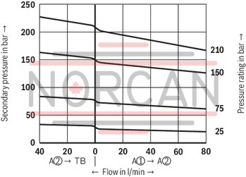
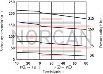
(measured with HLP46, ϑOil = 40 ±5 °C)
pA-qV characteristic curves
Version "A"
pA-qV characteristic curves
Version “B” and “P”
Notice!
The curve development is maintained if the pressure is set lower according to the pressure rating.
Δpmin-qV characteristic curves
Version "A"

Δpmin-qV characteristic curves
Version “B” and “P”
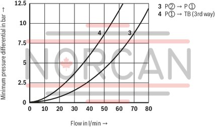
Δp-qV characteristic curves
Version "A"
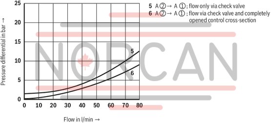
The characteristic curves apply to the pressure at the valve output pT = 0 barbar across the entire flow range.
|
➀ |
component side |
|
➁ |
plate side |
Type ZDR 10 DP…YM…
Type ZDR 10 DA…YM…
Type ZDR 10 DB…YM…
Type ZDR 10 DA…Y…
Notice!
Deviating from ISO 4401, port T is referred to as TA and port T1 is referred to as TB in this data sheet.
Dimensions in mm
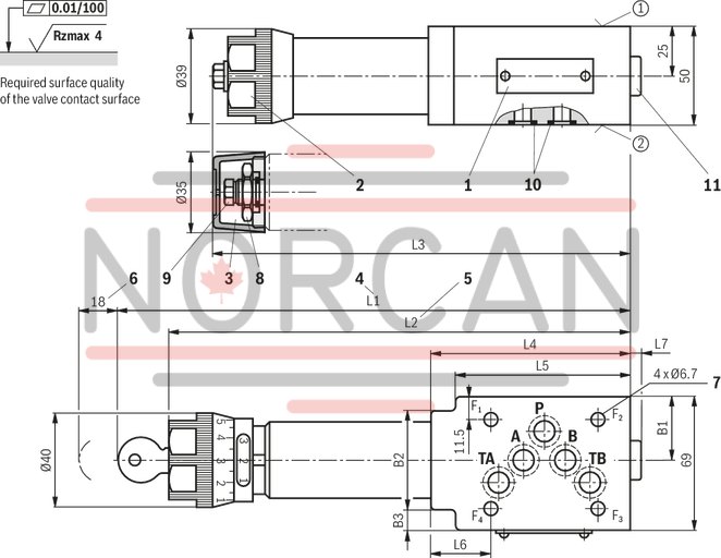
|
Version |
L1 |
L2 |
L3 |
L4 |
L5 |
L6 |
L7 |
B1 |
B2 |
B3 |
|
mm |
mm |
mm |
mm |
mm |
mm |
mm |
mm |
mm |
mm |
|
| A | 254 | 230 | 210 | 104 | 93 | 31.5 | 3.8 | 32.9 | 51 | 12 |
| B, P | 242 | 218 | 198 | 91 | - | 18.5 | 15.8 | 35 | - | - |
|
1 |
Name plate |
|
2 |
Adjustment type "1" |
|
3 |
Adjustment type "2" |
|
4 |
Adjustment type "3" |
|
5 |
Adjustment type "7" |
|
6 |
Space required to remove the key |
|
7 |
Valve mounting bores |
|
8 |
Lock nut SW24 |
|
9 |
Hexagon SW10 |
|
10 |
Identical seal rings for ports A, B, P, TA, TB |
|
11 |
Pressure gauge connection G1/4; 12 mm deep; internal hexagon SW6 |
|
➀ |
component side – Porting pattern according to ISO 4401-05-04-0-05 |
|
➁ |
plate side – Porting pattern according to ISO 4401-05-04-0-05 |
Valve mounting screws (separate order)
4 hexagon socket head cap screws ISO 4762 - M6 - 10.9
Notices!
Length and tightening torque of the valve mounting screw must be calculated in connection with the components mounted underneath and above the sandwich plate valve. To port X and Y bored according to ISO 4401-05-05-0-05 (e. g. for pilot-operated directional valve NG 10), version “SO30” applies at the end of the ordering code! Deviating from ISO 4401, port T is referred to as TA and port T1 is referred to as TB in this data sheet.