


BOSCH REXROTH
R978912391
- BOSCH REXROTH
- Material:R978912391
- Model:VT-SR1-1X/4WEEE10 SO43A-1608
Due to extremely high demand, please call 877-366-7226 for availability
The Bosch Rexroth VT-SR1-1X/4WEEE10 SO43A-1608 (R978912391) is a sophisticated valve amplifier designed for precise control in hydraulic systems. This component features a push-pull output stage with bipolar transistors, which can be engaged or disengaged via an enable circuit relay, visually confirmed by an illuminated LED on the front plate. The unit's switching voltage is adjustable through jumpers, ensuring compatibility with various system requirements. Equipped with an I controller and a dither signal generator, the VT-SR1-1X/4WEEE10 SO43A-1608 ensures smooth operation and fine-tuning of the dither signal amplitude. The PD controller manages the prestage current command value while providing real-time feedback through an on-board measuring instrument. Additionally, this model includes an oscillatordemodulator for accurate control spool position sensing, tailored to specific valve types. For enhanced functionality, users can adjust the zero point externally and benefit from reverse polarity protection for the symmetric operating voltage. An optional PID controller offers advanced control options, including a switchable PI share and a backup relay with potential-free changeover contact for integrating additional control loops. Constructed in analog Eurocard format, this amplifier is compatible with WSEE , WRD X, and WRD X valves and requires stabilized auxiliary voltage if not equipped with onboard regulators. The PID controller settings and backup relay capacity are customizable to meet specific user requirements. This device represents a versatile solution for managing valve flow and main control spool position within hydraulic systems.
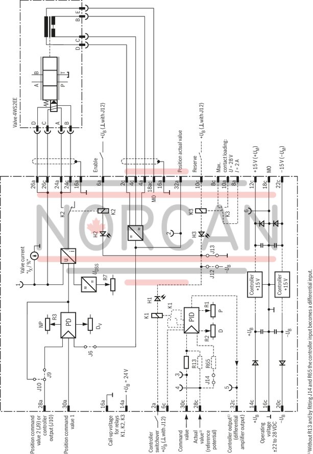
The valve amplifiers operate with a push-pull output stage with bipolar transistors. The output of this output stage can be connected or disconnected by means of an enable circuit (relay K2). The enable is indicated by the LED "H2" on the front plate being illuminated. The switching voltage of all relays is defined by means of jumpers J12 and J13 to either 0 V or +UB (factory +UB).
The output stage consists of an I controller with connected dither signal generator. The amplitude of the dither signal is set by means of R7. The pre-stage (current command value) is controlled via a PD controller. The actual current value returned is simultaneously indicated by the instrument on the front plate.
The oscillator/demodulator senses the control spool position. It is designed as pluggable board the parameters of which are adapted to the respective valve type.
The PD controller is supplied the position command value and the position command value and the actual position value with the D share of the controller only affecting the actual value (velocity feedback).
The zero point can be set via R3 (NP) from the front plate.
The required symmetric operating voltage +UB is protected against reversed polarity. If the board is not equipped with any voltage regulators for supply of the controller and position transducer electronics, an additional stabilized auxiliary voltage ±UM is required. The auxiliary voltage port is protected against reversed polarity up to a maximum current of 1 A.
As an option, the amplifier can be equipped with a PID controller (D share only affects the actual value) with a switchable PI share and a backup relay with potential-free changeover contact. This controller can be used to superimpose a further control loop (e.g. for drive control). The P and D share can be set at the front plate. The controller switching status is indicated by the LED "H1", the relay at LED "H3" (LEDs illuminated if relays are applied). The PID controller fitting is customer-specific and therefore has to be specified in the order in plain text. These amplifiers receive a special type designation upon delivery. The backup relay is loadable up to 28 V and 0.5 A.
|
01 |
Valve amplifier for servo valves with electrical position feedback |
VT-SR1 |
|
02 |
Component series 10 ... 19 (10 ... 19: unchanged installation and connection dimensions) |
1X |
|
03 |
Without ±15 V voltage regulator |
0 |
|
With ±15 V voltage regulator |
1 |
|
|
04 |
For valves: 4WRD 16-3X |
4WRD16-3X |
|
For valves: 4WRD 25-3X |
4WRD25-3X |
|
|
For valves: 4WS2EE 10 |
4WS2EE10 |
|
|
05 |
Further details in the plain text |
* |
|
01 |
02 |
03 |
04 |
05 |
|||
|
VT-SR1 |
‒ |
1X |
/ |
/ |
* |
General
|
Type / version |
VT-SR1-…/1/4WS2EE10 | VT-SR1-…/1/4WRD16-3X | VT-SR1-…/1/4WRD25-3X | |
|
Component series |
1X | |||
|
Type of electronics |
Analog | |||
|
Design |
Euro-card | |||
Voltage supply
|
Type / version |
VT-SR1-…/1/4WS2EE10 | VT-SR1-…/1/4WRD16-3X | VT-SR1-…/1/4WRD25-3X | ||||
|
Operating voltage |
with integrated voltage regulator |
UB |
V |
± 24 | |||
|
Upper limit value |
UB(t)max |
V |
± 28 | ||||
|
Lower limit value |
UB(t)min |
V |
± 22 | ||||
|
without integrated voltage regulator |
UB; UM |
V |
±24; ±15.0 | ||||
|
Upper limit value |
UB(t)max; UM(t)max |
V |
±28; ±15.2 | ||||
|
Lower limit value |
UB(t)min; UM(t)min |
V |
±22, ±14.8 | ||||
|
Current consumption |
max. |
Imax |
V |
0.15 A | |||
Analog inputs
|
Type / version |
VT-SR1-…/1/4WS2EE10 | VT-SR1-…/1/4WRD16-3X | VT-SR1-…/1/4WRD25-3X | ||||
|
Command value |
Voltage |
grounded on one side, first input 1) |
Ue |
V |
0 … ±10 | ||
|
grounded on one side, second input 2) |
Ue |
V |
0 … ±10 | ||||
|
Actual position value 1) |
Voltage |
Ue |
V |
0 … ±10 | |||
| 1) | RE = 50 kΩ |
| 2) | RE = 50 kΩ, J9 gesteckt |
Digital inputs
|
Type / version |
VT-SR1-…/1/4WS2EE10 | VT-SR1-…/1/4WRD16-3X | VT-SR1-…/1/4WRD25-3X | |||
|
Enable 1) |
On (active) |
Ue |
V |
+24 (with J13); 0 (with J12) | ||
|
Controller change-over 1) |
Ue |
V |
+24 (with J13); 0 (with J12) | |||
|
Backup relay 1) |
Ue |
V |
+24 (with J13); 0 (with J12) | |||
| 1) | RE = 700 Ω (relay) |
Analog outputs
|
Type / version |
VT-SR1-…/1/4WS2EE10 | VT-SR1-…/1/4WRD16-3X | VT-SR1-…/1/4WRD25-3X | |||
|
Valve flow command value |
Voltage |
UO |
-10 V ≙ +60 mA (J10 plugged) | |||
Solenoid outputs
|
Type / version |
VT-SR1-…/1/4WS2EE10 | VT-SR1-…/1/4WRD16-3X | VT-SR1-…/1/4WRD25-3X | |||
|
Solenoid current |
max. |
Imax |
mA |
60 | ||
|
Dither signal |
f |
Hz |
340 ±5 % (Ipp = 3 mA) | |||
Position transducer
|
Type / version |
VT-SR1-…/1/4WS2EE10 | VT-SR1-…/1/4WRD16-3X | VT-SR1-…/1/4WRD25-3X | ||
|
Oscillator frequency |
f |
kHz |
5 | 2.5 | |
Other information
|
Type / version |
VT-SR1-…/1/4WS2EE10 | VT-SR1-…/1/4WRD16-3X | VT-SR1-…/1/4WRD25-3X | |||
|
Relay |
Pickup voltage |
V |
+24 (UB) | |||
|
Nominal voltage |
U |
V |
26 | |||
|
Response voltage |
U |
V |
13 | |||
|
Step-back voltage |
U |
V |
1.3 ... 6.5 | |||
|
Switching time |
t |
ms |
4 | |||
|
Coil resistance at 25 °C |
R |
Ω |
700 | |||
|
Reference voltage |
Potentiometer supply |
U |
V |
±15 ±2 % (Imax = 150 mA) | ||
|
Anschlussart |
32-pole male multipoint connector, DIN 41612, design D | |||||
|
Ambient temperature range |
ϑ |
°C |
0 … 50 | |||
|
Storage temperature range |
ϑ |
°C |
-20 … 70 | |||
|
Weight |
m |
kg |
0.3 | |||
For applications outside these parameters, please consult us!


The amplifier card may only be unplugged and plugged when de-energized.
Command values may only be switched via relays with gold-plated contacts (low voltage, low currents).
Card relays may only be switched (enable, controller change-over, reserve) using contacts with a load capacity of approx. 40 V; 50 mA.
Always shield command and actual value cables; connect shielding to ground (⊥) on the card-side, open at one side.
Do not lay signal lines close to power lines.
Recommendation:
Also shield the solenoid conductors (to ⊥ on one side).
Up to a length of 50 m, use cable type LiYCY 1.5 mm2, for longer lengths please ask.