
SUN HYDRAULICS
CBBCCIV
$78.53 USD
- SUN HYDRAULICS
- Material:CBBCCIV
- Model:CBBC-CIV
- Summary:Cartridge
Quantity in stock: 0
***Disclaimer: The following summary contains information gathered from various sources such as product descriptions, technical specifications and catalogs. While efforts have been made to provide accurate details, inaccuracies may occur. It is advised to verify all information by contacting Sun Hydraulics directly.***
The Sun Hydraulics CBBCCIV (CBBCCIV) is a meticulously engineered counterbalance valve designed to manage the control of overrunning loads in hydraulic systems. This valve features a check valve that permits free flow from the directional valve port to the load port, while a direct-acting, pilot-assisted relief valve regulates flow from port to port. The pilot assist at port significantly reduces the effective setting of the relief valve based on the pilot ratio, enhancing operational efficiency and stability. Key specifications include a maximum recommended load pressure at maximum setting of 5000 psi (345 bar), with a factory-established maximum setting also at 5000 psi (345 bar). The pilot ratio is set at 3:1, ensuring precise control and responsiveness under varying load pressures. The valve's capacity reaches up to 22 gpm (83 L/min), suitable for substantial hydraulic flows. For installation and adjustments, the counterbalance valves are designed with an adjustment feature that requires counterclockwise turns to increase pressure settings, ensuring easy operation and maintenance. Additionally, this model incorporates Sun’s floating style construction which minimizes internal parts binding—this is crucial for maintaining consistent performance even when installation torque or cavity/cartridge machining variations occur. This product also boasts robust construction with positive seals between all ports, ensuring no leakage and long-term reliability in corrosive environments when configured with specific model code suffixes like AP for external stainless steel components or LH for external zinc-nickel plated components. Overall, the Sun Hydraulics CBBCCIV counterbalance valve is an essential component for enhancing machine stability and operational efficiency in hydraulic systems handling high-load pressures. Its design ensures it can be directly installed into actuator housings which improves circuit stiffness and protection against environmental factors.
The Sun Hydraulics CBBCCIV (CBBCCIV) is a meticulously engineered counterbalance valve designed to manage the control of overrunning loads in hydraulic systems. This valve features a check valve that permits free flow from the directional valve port to the load port, while a direct-acting, pilot-assisted relief valve regulates flow from port to port. The pilot assist at port significantly reduces the effective setting of the relief valve based on the pilot ratio, enhancing operational efficiency and stability. Key specifications include a maximum recommended load pressure at maximum setting of 5000 psi (345 bar), with a factory-established maximum setting also at 5000 psi (345 bar). The pilot ratio is set at 3:1, ensuring precise control and responsiveness under varying load pressures. The valve's capacity reaches up to 22 gpm (83 L/min), suitable for substantial hydraulic flows. For installation and adjustments, the counterbalance valves are designed with an adjustment feature that requires counterclockwise turns to increase pressure settings, ensuring easy operation and maintenance. Additionally, this model incorporates Sun’s floating style construction which minimizes internal parts binding—this is crucial for maintaining consistent performance even when installation torque or cavity/cartridge machining variations occur. This product also boasts robust construction with positive seals between all ports, ensuring no leakage and long-term reliability in corrosive environments when configured with specific model code suffixes like AP for external stainless steel components or LH for external zinc-nickel plated components. Overall, the Sun Hydraulics CBBCCIV counterbalance valve is an essential component for enhancing machine stability and operational efficiency in hydraulic systems handling high-load pressures. Its design ensures it can be directly installed into actuator housings which improves circuit stiffness and protection against environmental factors.
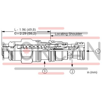
Counterbalance valves with pilot assist are meant to control an overrunning load. The check valve allows free flow from the directional valve (port 2) to the load (port 1) while a direct-acting, pilot-assisted relief valve controls flow from port 1 to port 2. Pilot assist at port 3 lowers the effective setting of the relief valve at a rate determined by the pilot ratio.
Other names for this valve include motion control valve and over center valve.
- Counterbalance valves should be set at least 1.3 times the maximum load induced pressure.
- Turn adjustment clockwise to decrease setting and release load.
- Full clockwise setting is less than 200 psi (14 bar).
- Backpressure at port 2 adds to the effective relief setting at a ratio of 1 plus the pilot ratio times the backpressure.
- Reseat exceeds 85% of set pressure when the valve is standard set. Settings lower than the standard set pressure may result in lower reseat percentages.
- Sun counterbalance cartridges can be installed directly into a cavity machined in an actuator housing for added protection and improved stiffness in the circuit.
- Two check valve cracking pressures are available. Use the 25 psi (1,7 bar) check unless actuator cavitation is a concern.
- This valve has positive seals between all ports.
- All 3-port counterbalance, load control, and pilot-to-open check cartridges are physically interchangeable (i.e. same flow path, same cavity for a given frame size).
- Corrosion resistant cartridge valves are intended for use in corrosive environments and are identified by the model code suffix /AP for external stainless steel components, or /LH for external zinc-nickel plated components. See the CONFIGURATION section for all options. For further details, please see the Materials of Construction page located under TECH RESOURCES.
- Incorporates the Sun floating style construction to minimize the possibility of internal parts binding due to excessive installation torque and/or cavity/cartridge machining variations.
| Cavity | T-11A |
| Series | 1 |
| Capacity | 10 gpm40 L/min. |
| Pilot Ratio | 3:13:1 |
| Maximum Recommended Load Pressure at Maximum Setting | 3075 psi215 bar |
| Maximum Setting | 4000 psi280 bar |
| Factory Pressure Settings Established at | 2 in³/min.30 cc/min. |
| Maximum Valve Leakage at Reseat | 5 drops/min.0,3 cc/min. |
| Adjustment - Number of Counterclockwise Turns to Increase Setting | 3.753.75 |
| Operating Characteristic | Semi-restrictiveSemi-restrictive |
| Reseat | >85% of setting>85% of setting |
| Valve Hex Size | 7/8 in.22,2 mm |
| Valve Installation Torque | 30 - 35 lbf ft41 - 47 Nm |
| Adjustment Screw Internal Hex Size | 5/32 in.4 mm |
| Locknut Hex Size | 9/16 in.15 mm |
| Locknut Torque | 80 - 90 lbf in.9 - 10 Nm |
| Model Weight | .40 lb0,20 kg |
| Seal kit - Cartridge | Viton: 990-011-006 |
Show FAQ