
SUN HYDRAULICS
CBBYCAV
$83.79 USD
- SUN HYDRAULICS
- Material:CBBYCAV
- Model:CBBY-CAV
- Summary:Cartridge
Quantity in stock: 0
***Disclaimer: The following summary contains information gathered from various sources such as product descriptions, technical specifications and catalogs. While efforts have been made to provide accurate details, inaccuracies may occur. It is advised to verify all information by contacting Sun Hydraulics directly.***
The Sun Hydraulics CBBYCAV (CBBYCAV) is a sophisticated counterbalance valve designed to manage the control of overrunning loads in hydraulic systems. It features a check valve that allows free flow from the directional valve port 2 to the load port 1, while a direct-acting, pilot-assisted relief valve controls flow from port 1 to port 2. The pilot assist at port 3 modifies the relief valve setting according to the pilot ratio, enhancing the valve’s efficiency and response under varying load conditions. This model is engineered for applications requiring precise motion control such as in mobile equipment, lifting devices, and industrial machinery where smooth operation and safety are critical. The CBBYCAV can handle a maximum flow of 5 gpm (20 L/min) and supports pressures up to 4000 psi (280 bar), making it suitable for high-pressure applications. Its design includes features like an adjustable setting via an external screw, providing flexibility in system tuning without disassembly. Sun Hydraulics has incorporated a floating style construction into this model to minimize potential internal binding due to excessive installation torque or variations in cavity machining, ensuring reliable performance and longevity. Additionally, options for corrosion-resistant configurations are available for use in harsh environments. Overall, the Sun Hydraulics CBBYCAV counterbalance valve is essential for systems where load stability and precise hydraulic control are necessary. Its robust construction and adaptable settings make it a versatile choice for a wide range of industrial applications.
The Sun Hydraulics CBBYCAV (CBBYCAV) is a sophisticated counterbalance valve designed to manage the control of overrunning loads in hydraulic systems. It features a check valve that allows free flow from the directional valve port 2 to the load port 1, while a direct-acting, pilot-assisted relief valve controls flow from port 1 to port 2. The pilot assist at port 3 modifies the relief valve setting according to the pilot ratio, enhancing the valve’s efficiency and response under varying load conditions. This model is engineered for applications requiring precise motion control such as in mobile equipment, lifting devices, and industrial machinery where smooth operation and safety are critical. The CBBYCAV can handle a maximum flow of 5 gpm (20 L/min) and supports pressures up to 4000 psi (280 bar), making it suitable for high-pressure applications. Its design includes features like an adjustable setting via an external screw, providing flexibility in system tuning without disassembly. Sun Hydraulics has incorporated a floating style construction into this model to minimize potential internal binding due to excessive installation torque or variations in cavity machining, ensuring reliable performance and longevity. Additionally, options for corrosion-resistant configurations are available for use in harsh environments. Overall, the Sun Hydraulics CBBYCAV counterbalance valve is essential for systems where load stability and precise hydraulic control are necessary. Its robust construction and adaptable settings make it a versatile choice for a wide range of industrial applications.
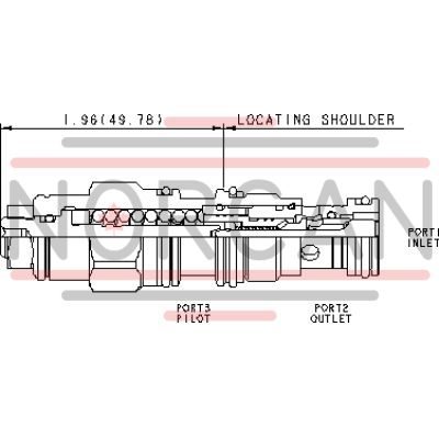
Counterbalance valves with pilot assist are meant to control an overrunning load. The check valve allows free flow from the directional valve (port 2) to the load (port 1) while a direct-acting, pilot-assisted relief valve controls flow from port 1 to port 2. Pilot assist at port 3 lowers the effective setting of the relief valve at a rate determined by the pilot ratio.
Other names for this valve include motion control valve and over center valve.
- Counterbalance valves should be set at least 1.3 times the maximum load induced pressure.
- Restrictive valves have no relief capacity other than as a thermal relief.
- Turn adjustment clockwise to decrease setting and release load.
- Full clockwise setting is less than 200 psi (14 bar).
- Backpressure at port 2 adds to the effective relief setting at a ratio of 1 plus the pilot ratio times the backpressure.
- Reseat exceeds 85% of set pressure when the valve is standard set. Settings lower than the standard set pressure may result in lower reseat percentages.
- Sun counterbalance cartridges can be installed directly into a cavity machined in an actuator housing for added protection and improved stiffness in the circuit.
- Two check valve cracking pressures are available. Use the 25 psi (1,7 bar) check unless actuator cavitation is a concern.
- This valve uses orifices to lower the pilot ratio and therefore will pass up to 40 in³/min./1000 psi (0,7 L/min./70 bar) between port 2 and port 3. This is a consideration in master-slave circuits and in the leak testing of valve-cylinder assemblies.
- All 3-port counterbalance, load control, and pilot-to-open check cartridges are physically interchangeable (i.e. same flow path, same cavity for a given frame size).
- Corrosion resistant cartridge valves are intended for use in corrosive environments and are identified by the model code suffix /AP for external stainless steel components, or /LH for external zinc-nickel plated components. See the CONFIGURATION section for all options. For further details, please see the Materials of Construction page located under TECH RESOURCES.
- Incorporates the Sun floating style construction to minimize the possibility of internal parts binding due to excessive installation torque and/or cavity/cartridge machining variations.
| Cavity | T-11A |
| Series | 1 |
| Capacity | 5 gpm20 L/min. |
| Pilot Ratio | 2:12:1 |
| Maximum Recommended Load Pressure at Maximum Setting | 3075 psi215 bar |
| Maximum Setting | 4000 psi280 bar |
| Factory Pressure Settings Established at | 2 in³/min.30 cc/min. |
| Maximum Valve Leakage at Reseat | 5 drops/min.0,3 cc/min. |
| Adjustment - Number of Counterclockwise Turns to Increase Setting | 3.753.75 |
| Operating Characteristic | RestrictiveRestrictive |
| Reseat | >85% of setting>85% of setting |
| Valve Hex Size | 7/8 in.22,2 mm |
| Valve Installation Torque | 30 - 35 lbf ft41 - 47 Nm |
| Adjustment Screw Internal Hex Size | 5/32 in.4 mm |
| Locknut Hex Size | 9/16 in.15 mm |
| Locknut Torque | 80 - 90 lbf in.9 - 10 Nm |
| Model Weight | .40 lb0,20 kg |
| Seal kit - Cartridge | Viton: 990-011-006 |
Show FAQ