
SUN HYDRAULICS
CBCLCJV
$84.78 USD
- SUN HYDRAULICS
- Material:CBCLCJV
- Model:CBCL-CJV
- Summary:Cartridge
Quantity in stock: 0
***Disclaimer: The following summary contains information gathered from various sources such as product descriptions, technical specifications and catalogs. While efforts have been made to provide accurate details, inaccuracies may occur. It is advised to verify all information by contacting Sun Hydraulics directly.***
The Sun Hydraulics CBCLCJV (CBCLCJV) is a sophisticated counterbalance valve designed for hydraulic systems requiring precise control over overrunning loads. This valve features a check valve that permits free flow from the directional valve port 2 to the load port 1, while a direct-acting, pilot-assisted relief valve manages the flow from port 1 to port 2. The pilot assist at port 3 effectively reduces the relief valve setting according to a predetermined pilot ratio, enhancing the functionality and responsiveness of the system. The CBCLCJV is engineered to maintain stability and prevent load drop in hydraulic circuits, with an adjustment mechanism that allows for fine-tuning of pressure settings. It should be calibrated to at least 1.3 times the maximum load-induced pressure to ensure optimal performance. The design includes features such as positive seals between all ports and a reseat capability that exceeds 85% of set pressure under standard conditions, ensuring reliable operation and minimal leakage. Additionally, this model can be directly installed into actuator housings due to its robust cartridge design, which improves circuit stiffness and protects system integrity. Available in two check valve cracking pressures (25 psi and 4 psi), it accommodates various application needs regarding actuator cavitation concerns. The CBCLCJV also incorporates Sun’s floating style construction which minimizes potential internal part binding caused by installation torque or machining variations in the cavity. This counterbalance valve is an ideal choice for applications demanding high precision and reliability in controlling hydraulic loads, ensuring both safety and efficiency in operations.
The Sun Hydraulics CBCLCJV (CBCLCJV) is a sophisticated counterbalance valve designed for hydraulic systems requiring precise control over overrunning loads. This valve features a check valve that permits free flow from the directional valve port 2 to the load port 1, while a direct-acting, pilot-assisted relief valve manages the flow from port 1 to port 2. The pilot assist at port 3 effectively reduces the relief valve setting according to a predetermined pilot ratio, enhancing the functionality and responsiveness of the system. The CBCLCJV is engineered to maintain stability and prevent load drop in hydraulic circuits, with an adjustment mechanism that allows for fine-tuning of pressure settings. It should be calibrated to at least 1.3 times the maximum load-induced pressure to ensure optimal performance. The design includes features such as positive seals between all ports and a reseat capability that exceeds 85% of set pressure under standard conditions, ensuring reliable operation and minimal leakage. Additionally, this model can be directly installed into actuator housings due to its robust cartridge design, which improves circuit stiffness and protects system integrity. Available in two check valve cracking pressures (25 psi and 4 psi), it accommodates various application needs regarding actuator cavitation concerns. The CBCLCJV also incorporates Sun’s floating style construction which minimizes potential internal part binding caused by installation torque or machining variations in the cavity. This counterbalance valve is an ideal choice for applications demanding high precision and reliability in controlling hydraulic loads, ensuring both safety and efficiency in operations.
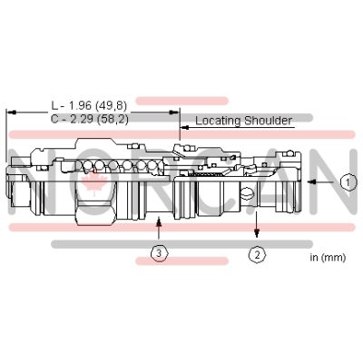
Counterbalance valves with pilot assist are meant to control an overrunning load. The check valve allows free flow from the directional valve (port 2) to the load (port 1) while a direct-acting, pilot-assisted relief valve controls flow from port 1 to port 2. Pilot assist at port 3 lowers the effective setting of the relief valve at a rate determined by the pilot ratio.
Other names for this valve include motion control valve and over center valve.
- Counterbalance valves should be set at least 1.3 times the maximum load induced pressure.
- Turn adjustment clockwise to decrease setting and release load.
- Full clockwise setting is less than 200 psi (14 bar).
- Backpressure at port 2 adds to the effective relief setting at a ratio of 1 plus the pilot ratio times the backpressure.
- Reseat exceeds 85% of set pressure when the valve is standard set. Settings lower than the standard set pressure may result in lower reseat percentages.
- Cartridges configured with EPDM seals are for use in systems with phosphate ester fluids. Exposure to petroleum based fluids, greases and lubricants will damage the seals.
- Sun counterbalance cartridges can be installed directly into a cavity machined in an actuator housing for added protection and improved stiffness in the circuit.
- Two check valve cracking pressures are available. Use the 25 psi (1,7 bar) check unless actuator cavitation is a concern.
- This valve has positive seals between all ports.
- All 3-port counterbalance, load control, and pilot-to-open check cartridges are physically interchangeable (i.e. same flow path, same cavity for a given frame size).
- Corrosion resistant cartridge valves are intended for use in corrosive environments and are identified by the model code suffix /AP for external stainless steel components, or /LH for external zinc-nickel plated components. See the CONFIGURATION section for all options. For further details, please see the Materials of Construction page located under TECH RESOURCES.
- Incorporates the Sun floating style construction to minimize the possibility of internal parts binding due to excessive installation torque and/or cavity/cartridge machining variations.
| Cavity | T-11A |
| Series | 1 |
| Capacity | 15 gpm60 L/min. |
| Pilot Ratio | 2.3:12.3:1 |
| Maximum Recommended Load Pressure at Maximum Setting | 3850 psi270 bar |
| Maximum Setting | 5000 psi350 bar |
| Factory Pressure Settings Established at | 2 in³/min.30 cc/min. |
| Maximum Valve Leakage at Reseat | 5 drops/min.0,3 cc/min. |
| Adjustment - Number of Counterclockwise Turns to Increase Setting | 3.753.75 |
| Operating Characteristic | StandardStandard |
| Reseat | >85% of setting>85% of setting |
| Valve Hex Size | 7/8 in.22,2 mm |
| Valve Installation Torque | 30 - 35 lbf ft41 - 47 Nm |
| Adjustment Screw Internal Hex Size | 5/32 in.4 mm |
| Locknut Hex Size | 9/16 in.15 mm |
| Locknut Torque | 80 - 90 lbf in.9 - 10 Nm |
| Model Weight | .40 lb0,20 kg |
| Seal kit - Cartridge | Viton: 990-011-006 |
Show FAQ