

SUN HYDRAULICS
PPFBCNN
$134.33 USD
- SUN HYDRAULICS
- Material:PPFBCNN
- Model:PPFB-CNN
- Summary:Cartridge
Quantity in stock: 0
***Disclaimer: The following summary contains information gathered from various sources such as product descriptions, technical specifications and catalogs. While efforts have been made to provide accurate details, inaccuracies may occur. It is advised to verify all information by contacting Sun Hydraulics directly.***
The Sun Hydraulics PPFBCNN (Material Number: PPFBCNN) is a pilot-operated, pressure-reducing/relieving valve designed to manage high primary pressures at the inlet port and maintain a constant reduced pressure at the outlet, with full-flow relief capabilities. This valve is particularly stable, exhibiting low hysteresis and exceptionally flat pressure-flow characteristics. It is not intended for fast-acting applications; for such needs, direct-acting valves are recommended. The valve features a maximum operating pressure of 5000 psi (350 bar) and is suitable for systems with phosphate ester fluids due to its EPDM seals, which are sensitive to petroleum-based substances. The PPFBCNN model incorporates Sun's floating style construction to prevent internal binding from installation torque or machining variations. The valve's control pilot flow ranges between 10 to 15 in\u00b3/min (0.16 to 0.25 L/min), with an adjustment capability of up to 5.5 clockwise turns to increase settings. It has a hex size of 1 1/8 inches (28.6 mm) for installation and requires a torque setting between 45 and 50 lbf-ft (61 to 68 Nm). The model weighs approximately 0.60 lb (0.30 kg), and its seal kit is available under the Viton specification: 990202006. This cartridge-style valve can be physically interchanged across three-port configurations within its frame size, although it is advised that a full-capacity return line port be used when deploying reducing/relieving cartridges in certain mounting configurations. If reverse flow from reduced pressure port to inlet port is necessary, additional check valves may be required in the circuit design. Additionally, for critical pilot flow consumption scenarios, direct-acting reducing/relieving valves might be more appropriate choices due to their operational characteristics.
The Sun Hydraulics PPFBCNN (Material Number: PPFBCNN) is a pilot-operated, pressure-reducing/relieving valve designed to manage high primary pressures at the inlet port and maintain a constant reduced pressure at the outlet, with full-flow relief capabilities. This valve is particularly stable, exhibiting low hysteresis and exceptionally flat pressure-flow characteristics. It is not intended for fast-acting applications; for such needs, direct-acting valves are recommended. The valve features a maximum operating pressure of 5000 psi (350 bar) and is suitable for systems with phosphate ester fluids due to its EPDM seals, which are sensitive to petroleum-based substances. The PPFBCNN model incorporates Sun's floating style construction to prevent internal binding from installation torque or machining variations. The valve's control pilot flow ranges between 10 to 15 in\u00b3/min (0.16 to 0.25 L/min), with an adjustment capability of up to 5.5 clockwise turns to increase settings. It has a hex size of 1 1/8 inches (28.6 mm) for installation and requires a torque setting between 45 and 50 lbf-ft (61 to 68 Nm). The model weighs approximately 0.60 lb (0.30 kg), and its seal kit is available under the Viton specification: 990202006. This cartridge-style valve can be physically interchanged across three-port configurations within its frame size, although it is advised that a full-capacity return line port be used when deploying reducing/relieving cartridges in certain mounting configurations. If reverse flow from reduced pressure port to inlet port is necessary, additional check valves may be required in the circuit design. Additionally, for critical pilot flow consumption scenarios, direct-acting reducing/relieving valves might be more appropriate choices due to their operational characteristics.
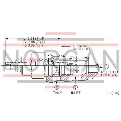
Pilot-operated, pressure reducing/relieving valves reduce a high primary pressure at the inlet (port 2) to a constant reduced pressure at port 1, with a full-flow relief function from port 1 to tank (port 3).
- Pressure at port 3 is directly additive to the valve setting at a 1:1 ratio and should not exceed 3000 psi (210 bar).
- Maximum pressure at port 3 should be limited to 3000 psi (210 bar).
- Recommended maximum inlet pressure is determined by the adjustment range. Ranges D, E, N, and Q are tested with a 2000 psi (140 bar) maximum differential between inlet and reduced pressure. Ranges A, B, and H are tested with a 3000 psi (210 bar) maximum differential between inlet and reduced pressure. Ranges C and W are tested with 5000 psi (350 bar) of inlet pressure.
- Pilot operated valves exhibit exceptionally flat pressure/flow characteristics, are very stable and have low hysteresis.
- Pilot operated reducing, reducing/relieving valves by nature are not fast acting valves. For superior dynamic response, consider direct acting valves.
- W and Y controls (where applicable) can be specified with or without a special setting. When no special setting is specified, the valve is adjustable throughout its full range using the W or Y control. When a special setting is specified, this setting represents the maximum setting of the valve.
- Cartridges configured with EPDM seals are for use in systems with phosphate ester fluids. Exposure to petroleum based fluids, greases and lubricants will damage the seals.
- All three-port pressure reducing and reducing/relieving cartridges are physically interchangeable (i.e. same flow path, same cavity for a given frame size). When considering mounting configurations, it is sometimes recommended that a full capacity return line (port 3) be used with reducing/relieving cartridges.
- Full reverse flow from reduced pressure (port 1) to inlet (port 2) may cause the main spool to close. If reverse free flow is required in the circuit, consider adding a separate check valve to the circuit.
- If pilot flow consumption is critical, consider using direct acting reducing/relieving valves.
- Incorporates the Sun floating style construction to minimize the possibility of internal parts binding due to excessive installation torque and/or cavity/cartridge machining variations.
| Cavity | T-2A |
| Series | 2 |
| Capacity | 20 gpm80 L/min. |
| Factory Pressure Settings Established at | blocked control port (dead headed)blocked control port (dead headed) |
| Maximum Operating Pressure | 5000 psi350 bar |
| Control Pilot Flow | 10 - 15 in³/min.0,16 - 0,25 L/min. |
| Adjustment - Number of Clockwise Turns to Increase Setting | 55 |
| Valve Hex Size | 1 1/8 in.28,6 mm |
| Valve Installation Torque | 45 - 50 lbf ft61 - 68 Nm |
| Adjustment Screw Internal Hex Size | 5/32 in.4 mm |
| Locknut Hex Size | 9/16 in.15 mm |
| Locknut Torque | 80 - 90 lbf in.9 - 10 Nm |
| Model Weight | .60 lb0,30 kg |
| Seal kit - Cartridge | Viton: 990-202-006 |
Show FAQ
Additional Resources
- Series 4 PLUS Cartridges Offer Higher Flows with Lower Pressure Losses
- Sun Offers Zinc-Nickel Plating for Corrosion Resistance
- Sun Cartridges with EPDM Seals
- QuickDesign with SmartConnect Offers Drag-and-Drop Schematic Tool
- Sun Expands Corrosion-Resistant Solutions
- Manufacturing Sun Cartridge Cavities
- Reducing and Reducing/Relieving Valves
- Performance Data
- Sun's Floating Style Screw-In Cartridge
- Units of Measure, Settings, and Conversions
- Sun Model Code Explanation; 999-901-334
- Cavity Information (S-171) and Tooling
- Cartridges: Materials of Construction
- Fluid and Temperature Recommendations
Notes:
- Maximum pressure differentials for spring ranges: A and B are 3000 psi (210 bar) N and Q are 2000 psi (140 bar) W is 5000 psi (350 bar)inlet pressure
- For Series 1 cartridges configured with an O control (panel mount handknob), a .75 in. (19 mm) diameter hole is required in the panel.