
SUN HYDRAULICS
PSDPMDN612
$245.22 USD
- SUN HYDRAULICS
- Material:PSDPMDN612
- Model:PSDP-MDN@612
- Summary:Cartridge
Quantity in stock: 0
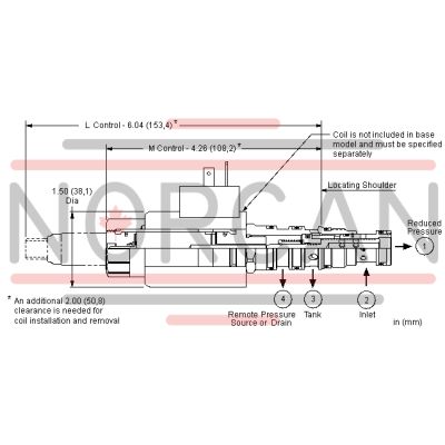
The Sun Hydraulics PSDPMDN612 (Material Number: PSDPMDN612) is an electroproportional, direct-acting reducer-reliever valve designed to reduce high primary pressure at inlet port 2 to a constant reduced pressure at port 1, while offering a full flow relief function from port 1 to tank port 3. The valve is initially set in the relieving mode, and energizing the coil facilitates connection between ports 2 and 1. As current increases, the reduced pressure at port 1 also increases proportionally. If the pressure at port 1 surpasses the coil-induced setting, it is relieved to port 3. The valve's design ensures it remains insensitive to pressure at port 3 due to draining at port 4. This feature contributes to low oil consumption during transition between reducing and relieving states. Manual control options are available for emergency settings or boosting valve settings during power failures. The valve operates efficiently under maximum pressures of up to 3000 psi (210 bar) at port 3 and can handle inlet pressures up to 5000 psi (350 bar). It is suitable for accumulator circuits as it minimizes secondary circuit leakage due to its absence of pilot control flow. The direct-acting nature ensures reliable performance even in contaminated systems or dead-headed conditions. For optimized functionality, an amplifier with current sensing and adjustable dither between 100-250 Hz is recommended. Additionally, reverse flow from reduced pressure port 1 back to inlet port 2 may close the main spool; hence, a separate check valve might be necessary for circuits requiring reverse free flow. The product incorporates Sun's floating style construction which reduces internal binding risks due to installation torque or machining variations, ensuring consistent performance across various applications.
This electro-proportional, direct-acting reducer/reliever valve reduces a high primary pressure at the inlet (port 2) to a constant reduced pressure at port 1, with a full flow relief function from port 1 to tank (port 3). The valve is biased to the relieving mode. Energizing the coil connects port 2 to port 1. Increasing the current to the coil will proportionally increase the reduced pressure at port 1. If pressure at port 1 exceeds the setting induced by the coil, pressure at port 1 is relieved to port 3. Draining port 4 makes the valve insensitive to pressure at port 3. This valve is closed in the transition between reducing and relieving resulting in very low consumption of oil. Optional full manual control is available.
- Maximum pressure at port 3 should be limited to 3000 psi (210 bar).
- All spring ranges are tested for correct operation with 5000 psi (350 bar) inlet pressure.
- Suitable for accumulator circuits since the absence of pilot control flow results in reduced secondary circuit leakage.
- Direct acting concept provides highly reliable operation in contaminated systems, especially at dead headed conditions.
- Leakage specified in Technical Data is out of port 3 with a supply pressure of 2000 psi (140 bar) and the valve set at mid range. This leakage is directly proportional to pressure differential and inversely proportional to viscosity expressed in centistokes.
- The transition from reducing to relieving is closed. The result is very low leakage. However, there is a transitional step increase in pressure between reducing and relieving modes. This step equals about 5% of the high end of the adjustment range, independent of the valve setting.
- For optimum performance, an amplifier with current sensing and adjustable dither should be used. Dither should be adjustable between 100 - 250 Hz.
- Full reverse flow from reduced pressure (port 1) to inlet (port 2) may cause the main spool to close. If reverse free flow is required in the circuit, consider adding a separate check valve to the circuit.
- Uses for the 'L' manual screw adjustment include: emergency valve setting during power failure or alternatively boosting the valve setting
- With the 'L' adjustment screw, all ranges are factory set at zero (adjustment screw fully backed out). With the coil de-energized, clockwise adjustment of the screw will increase the spring bias load up to the maximum setting for that range. With the coil energized, any mechanical pressure setting is directly additive to the coil induced value.
- By controlling the pressure at the drain (port 4), the effective setting of the valve can be increased over the nominal valve setting.
- Pressure on the drain (port 4) is directly additive to the valve setting at a 1:1 ratio and should not exceed 3000 psi (210 bar).
- Incorporates the Sun floating style construction to minimize the possibility of internal parts binding due to excessive installation torque and/or cavity/cartridge machining variations.
| Cavity | T-21A |
| Series | 1 |
| Capacity | 5 gpm20 L/min. |
| Maximum Operating Pressure | 5000 psi350 bar |
| Maximum Valve Leakage at 110 SUS (24 cSt) | 2.5 in³/min.41 cc/min. |
| Optimum Inlet Pressure | 3000 psi210 bar |
| Adjustment - Number of Clockwise Turns to Increase Setting | 55 |
| Solenoid Tube Diameter | .75 in.19 mm |
| Valve Hex Size | 7/8 in.22,2 mm |
| Valve Installation Torque | 30 - 35 lbf ft41 - 47 Nm |
| Adjustment Screw Internal Hex Size | 5/32 in.4 mm |
| Locknut Hex Size | 9/16 in.15 mm |
| Locknut Torque | 80 - 90 lbf in.9 - 10 Nm |
| Model Weight (with coil) | 1.20 lb0,55 kg |
| Seal kit - Cartridge | Viton: 990-021-006 |
| Seal and nut kit - Coil | Viton: 990-770-006Viton: 990-770-006 |
Show FAQ
Additional Resources
- Weatherized Solenoid Valves for Harsh Environments
- Configure Your Bluetooth Embedded Amplifier with AmpSet Blue™
- Series 4 PLUS Cartridges Offer Higher Flows with Lower Pressure Losses
- QuickDesign with SmartConnect Offers Drag-and-Drop Schematic Tool
- Electro-Proportional Basics Explained
- Sun Offers Zinc-Nickel Plating for Corrosion Resistance
- Sun Expands Corrosion-Resistant Solutions
- Sun Cartridges with EPDM Seals
- Solenoid Coils for Switching and Proportional Valves
- Reducing and Reducing/Relieving Valves
- Proportional Amplifiers and Ancillary Products
- Manufacturing Sun Cartridge Cavities
- Electro-Proportional Cartridge Valves
- Sun's Floating Style Screw-In Cartridge
- Fluid and Temperature Recommendations
- Sun Model Code Explanation; 999-901-334
- Performance Data
- Cartridges: Materials of Construction
- Units of Measure, Settings, and Conversions
- Electro-Proportional Terms and Definitions
- Cavity Information (S-171) and Tooling
Notes:
- Please verify cartridge clearance requirements when choosing a Sun manifold. Different valve controls and coils require different clearances.