
SUN HYDRAULICS
RVBBLWV
$106.53 USD
- SUN HYDRAULICS
- Material:RVBBLWV
- Model:RVBB-LWV
- Summary:Cartridge
Quantity in stock: 0
***Disclaimer: The following summary contains information gathered from various sources such as product descriptions, technical specifications and catalogs. While efforts have been made to provide accurate details, inaccuracies may occur. It is advised to verify all information by contacting Sun Hydraulics directly.***
The Sun Hydraulics RVBBLWV (RVBBLWV) is a three-port, normally closed modulating element with relief capabilities designed to provide dual functions when used in conjunction with an external orifice. As a bypass compensator, this valve controls priority flow into a circuit, determined by the external orifice, while diverting excess input flow to the tank port 2. Additionally, it acts as a standard relief valve if the inlet pressure at port 1 reaches the valve setting. The compensating pressure for all ranges is set at 50 psi (3.5 bar). Performance is illustrated through a curve where the X-axis represents system pressure and the Y-axis denotes the pressure differential across the control orifice, with curves indicating various bypass flows. The valve's capacity and performance are primarily influenced by bypass flow rather than control flow. This model fits into cavity T-163A and has a series 0 capacity of 5 gpm (20 L/min). It operates under a maximum pressure of 5000 psi (350 bar) and features a typical response time of 10 ms. Valve leakage is minimal at 2 in\u00b3/min (30 cc/min) at 1000 psi (70 bar). The adjustment for increasing settings involves up to five clockwise turns, with specific torque requirements for installation and locknut adjustments. Weighing approximately .30 lb (.15 kg), it utilizes Viton seals for cartridge applications. This versatile component is ideal for applications requiring precise flow control and reliable over-pressure protection within hydraulic systems.
The Sun Hydraulics RVBBLWV (RVBBLWV) is a three-port, normally closed modulating element with relief capabilities designed to provide dual functions when used in conjunction with an external orifice. As a bypass compensator, this valve controls priority flow into a circuit, determined by the external orifice, while diverting excess input flow to the tank port 2. Additionally, it acts as a standard relief valve if the inlet pressure at port 1 reaches the valve setting. The compensating pressure for all ranges is set at 50 psi (3.5 bar). Performance is illustrated through a curve where the X-axis represents system pressure and the Y-axis denotes the pressure differential across the control orifice, with curves indicating various bypass flows. The valve's capacity and performance are primarily influenced by bypass flow rather than control flow. This model fits into cavity T-163A and has a series 0 capacity of 5 gpm (20 L/min). It operates under a maximum pressure of 5000 psi (350 bar) and features a typical response time of 10 ms. Valve leakage is minimal at 2 in\u00b3/min (30 cc/min) at 1000 psi (70 bar). The adjustment for increasing settings involves up to five clockwise turns, with specific torque requirements for installation and locknut adjustments. Weighing approximately .30 lb (.15 kg), it utilizes Viton seals for cartridge applications. This versatile component is ideal for applications requiring precise flow control and reliable over-pressure protection within hydraulic systems.
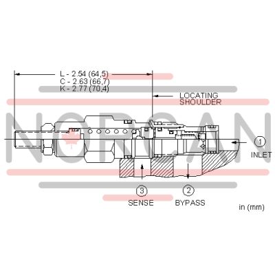
Three-port normally closed modulating elements with relief provide two functions when combined with an external orifice. The mainstage is a bypass compensator that controls a priority flow into the circuit, determined by the external orifice. Input flow in excess of the priority flow is bypassed to tank (port 2). If the inlet (port 1) pressure rises to the valve setting, the valve operates as a normal relief valve.
- Compensating pressure for all ranges is 50 psi (3,5 bar).
- Explanation of the performance curve: The X axis is system pressure. The Y axis shows the pressure differential that the valve creates across the control orifice. The curves represent various bypass flows (pump flow minus control flow). The capacity and performance of this valve is determined by the bypass flow, control flow is not a factor.
| Cavity | T-163A |
| Series | 0 |
| Capacity | 5 gpm20 L/min. |
| Factory Pressure Settings Established at | 4 gpm15 L/min. |
| Maximum Operating Pressure | 5000 psi350 bar |
| Response Time - Typical | 10 ms10 ms |
| Maximum Valve Leakage at 110 SUS (24 cSt) | 2 in³/min.@1000 psi30 cc/min.@70 bar |
| Adjustment - Number of Clockwise Turns to Increase Setting | 55 |
| Valve Hex Size | 3/4 in.19,1 mm |
| Valve Installation Torque | 20 - 25 lbf ft27 - 33 Nm |
| Adjustment Screw Internal Hex Size | 5/32 in.4 mm |
| Locknut Hex Size | 9/16 in.15 mm |
| Locknut Torque | 80 - 90 lbf in.9 - 10 Nm |
| Model Weight | .30 lb0,15 kg |
| Seal kit - Cartridge | Viton: 990-163-006 |
Show FAQ
Additional Resources
- Sun Cartridges with EPDM Seals
- QuickDesign with SmartConnect Offers Drag-and-Drop Schematic Tool
- Sun Expands Corrosion-Resistant Solutions
- Series 4 PLUS Cartridges Offer Higher Flows with Lower Pressure Losses
- Sun Offers Zinc-Nickel Plating for Corrosion Resistance
- Manufacturing Sun Cartridge Cavities
- Cartridges: Materials of Construction
- Cavity Information (S-171) and Tooling
- Fluid and Temperature Recommendations
- Sun's Floating Style Screw-In Cartridge
- Performance Data
- Sun Model Code Explanation; 999-901-334
- Units of Measure, Settings, and Conversions