
SUN HYDRAULICS
RVCBKAV
$120.43 USD
- SUN HYDRAULICS
- Material:RVCBKAV
- Model:RVCB-KAV
- Summary:Cartridge
Quantity in stock: 0
***Disclaimer: The following summary contains information gathered from various sources such as product descriptions, technical specifications and catalogs. While efforts have been made to provide accurate details, inaccuracies may occur. It is advised to verify all information by contacting Sun Hydraulics directly.***
The Sun Hydraulics RVCBKAV (RVCBKAV) is a three-port, normally closed modulating element with relief functionality, offering dual operations when paired with an external orifice. Primarily, the mainstage acts as a bypass compensator that regulates priority flow into a circuit based on the external orifice, directing any excess input flow to tank port 2. Additionally, if the pressure at inlet port 1 exceeds the valve setting, it functions as a conventional relief valve. The compensating pressure varies across different ranges: 45 psi (3 bar) for A range, 30 psi (2 bar) for B range, and 100 psi (7 bar) for C range. The performance curve illustrates system pressure on the X-axis against the pressure differential across the control orifice on the Y-axis, with curves indicating various bypass flows\u2014highlighting that valve capacity is dictated by bypass flow rather than control flow. This model features a cavity T-11A series 1 with a capacity of up to 10 gpm (40 L/min), supporting maximum operating pressures of 5000 psi (350 bar). It boasts a typical response time of just 10 ms and exhibits minimal leakage at specific conditions. The adjustment mechanism allows for increased settings via clockwise turns, with detailed specifications such as valve hex size and installation torque provided for precision handling. Weighing .40 lb (.20 kg), it includes Viton seal kits and offers robust construction tailored for efficient hydraulic system integration.
The Sun Hydraulics RVCBKAV (RVCBKAV) is a three-port, normally closed modulating element with relief functionality, offering dual operations when paired with an external orifice. Primarily, the mainstage acts as a bypass compensator that regulates priority flow into a circuit based on the external orifice, directing any excess input flow to tank port 2. Additionally, if the pressure at inlet port 1 exceeds the valve setting, it functions as a conventional relief valve. The compensating pressure varies across different ranges: 45 psi (3 bar) for A range, 30 psi (2 bar) for B range, and 100 psi (7 bar) for C range. The performance curve illustrates system pressure on the X-axis against the pressure differential across the control orifice on the Y-axis, with curves indicating various bypass flows\u2014highlighting that valve capacity is dictated by bypass flow rather than control flow. This model features a cavity T-11A series 1 with a capacity of up to 10 gpm (40 L/min), supporting maximum operating pressures of 5000 psi (350 bar). It boasts a typical response time of just 10 ms and exhibits minimal leakage at specific conditions. The adjustment mechanism allows for increased settings via clockwise turns, with detailed specifications such as valve hex size and installation torque provided for precision handling. Weighing .40 lb (.20 kg), it includes Viton seal kits and offers robust construction tailored for efficient hydraulic system integration.
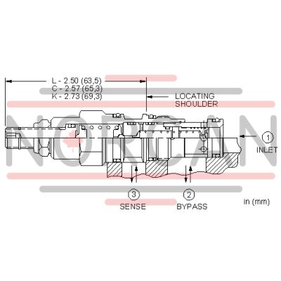
Three-port normally closed modulating elements with relief provide two functions when combined with an external orifice. The mainstage is a bypass compensator that controls a priority flow into the circuit, determined by the external orifice. Input flow in excess of the priority flow is bypassed to tank (port 2). If the inlet (port 1) pressure rises to the valve setting, the valve operates as a normal relief valve.
- Compensating pressure for the A range is 45 psi (3 bar), for the B range 30 psi (2 bar), and for the C range 100 psi (7 bar).
- Explanation of the performance curve: The X axis is system pressure. The Y axis shows the pressure differential that the valve creates across the control orifice. The curves represent various bypass flows (pump flow minus control flow). The capacity and performance of this valve is determined by the bypass flow, control flow is not a factor.
| Cavity | T-11A |
| Series | 1 |
| Capacity | 10 gpm40 L/min. |
| Factory Pressure Settings Established at | 4 gpm15 L/min. |
| Maximum Operating Pressure | 5000 psi350 bar |
| Response Time - Typical | 10 ms10 ms |
| Maximum Valve Leakage at 110 SUS (24 cSt) | 2 in³/min.@1000 psi30 cc/min.@70 bar |
| Adjustment - Number of Clockwise Turns to Increase Setting | 55 |
| Valve Hex Size | 7/8 in.22,2 mm |
| Valve Installation Torque | 30 - 35 lbf ft41 - 47 Nm |
| Adjustment Screw Internal Hex Size | 5/32 in.4 mm |
| Locknut Hex Size | 9/16 in.15 mm |
| Locknut Torque | 80 - 90 lbf in.9 - 10 Nm |
| Model Weight | .40 lb0,20 kg |
| Seal kit - Cartridge | Viton: 990-011-006 |
Show FAQ
Additional Resources
- Sun Cartridges with EPDM Seals
- QuickDesign with SmartConnect Offers Drag-and-Drop Schematic Tool
- Sun Expands Corrosion-Resistant Solutions
- Series 4 PLUS Cartridges Offer Higher Flows with Lower Pressure Losses
- Sun Offers Zinc-Nickel Plating for Corrosion Resistance
- Manufacturing Sun Cartridge Cavities
- Cartridges: Materials of Construction
- Cavity Information (S-171) and Tooling
- Fluid and Temperature Recommendations
- Sun's Floating Style Screw-In Cartridge
- Performance Data
- Sun Model Code Explanation; 999-901-334
- Units of Measure, Settings, and Conversions